majestic fireplace user manual

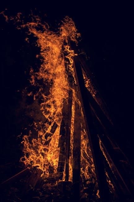
Welcome to the world of Majestic fireplaces, where elegance meets efficiency. Discover how these fireplaces blend style, comfort, and functionality for a cozy home experience.

1.1 Benefits of Using a Majestic Gas Fireplace

Majestic gas fireplaces offer a perfect blend of convenience, efficiency, and style, making them a popular choice for homeowners. They provide consistent, reliable heat with minimal maintenance compared to traditional wood-burning fireplaces. One of the key benefits is their energy efficiency, as they convert a higher percentage of fuel into usable heat. Additionally, they are environmentally friendly, producing fewer emissions than wood-burning alternatives. Majestic gas fireplaces also offer a realistic flame appearance, enhancing the ambiance of any room. They are easy to operate, with options for remote control or wall switches, and require no cleanup after use. Furthermore, they are versatile in design, fitting seamlessly into modern or traditional decor; Overall, Majestic gas fireplaces combine practicality and aesthetics, making them a superior choice for cozy and comfortable living spaces.

  • Energy-efficient heating solution.
  • Low maintenance compared to wood-burning fireplaces.
  • Environmentally friendly with reduced emissions.
  • Realistic flame appearance for ambiance.
  • Convenient operation with remote or wall controls.
  • Versatile design options to suit any home style.

1.2 Overview of Majestic Fireplace Models

Majestic fireplaces offer a diverse range of models designed to suit different preferences and needs. From sleek, modern designs to traditional styles, their lineup includes gas and electric fireplaces. Popular models like the Royalton Series and LDVR Series provide options for direct vent and vent-free installations, ensuring compatibility with various home setups. Each model is crafted with attention to detail, offering features like realistic flame patterns and efficient heat distribution. Additionally, Majestic fireplaces are available in different sizes, such as the BE36 and BE42 models, catering to both small and large spaces. Whether you prefer a cozy ambiance or a statement piece, Majestic ensures a perfect blend of functionality and aesthetics. Their commitment to quality and innovation makes them a trusted choice for homeowners seeking reliable and stylish heating solutions.

  • Wide selection of gas and electric models.
  • Modern and traditional design options.
  • Direct vent and vent-free installation choices.
  • Realistic flame patterns for enhanced ambiance.
  • Versatile sizing to fit any room.
  • High-quality construction and energy efficiency.

Safety Precautions

Majestic fireplaces require careful attention to safety guidelines to ensure optimal performance and risk reduction. Always follow installation and operational instructions to avoid potential hazards.

  • Avoid storing manuals or flammable materials near the fireplace.
  • Use only approved glass and components to prevent damage.

2.1 General Safety Guidelines

Ensuring the safe operation of your Majestic fireplace is paramount. Always maintain a safe distance from flammable materials and never store combustible items near the fireplace. Keep children and pets away from the appliance when in use. Avoid storing instruction manuals or any items inside the fireplace cavity, as high temperatures can cause damage or pose a fire risk.

  • Only use approved glass and components specifically designed for your Majestic fireplace.
  • Never operate the fireplace if it is damaged or malfunctions.
  • Ensure proper ventilation to prevent carbon monoxide buildup.
  • Follow all local safety regulations and installation requirements.

Regularly inspect your fireplace for wear and tear, and address any issues promptly to ensure safe and efficient operation.

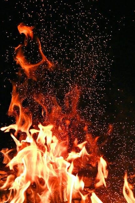
2.2 Risk of Fire: Important Warnings

Congratulations on selecting a Majestic gas fireplace, a clean alternative to wood burning. However, understanding the risk of fire is crucial for safe operation. High temperatures inside the fireplace cavity can damage stored items, posing a fire hazard. Never store instruction manuals or any combustible materials inside the cavity. Only use approved glass to prevent shattering and potential fires. Ensure your fireplace is installed by a qualified professional following local regulations to minimize fire risks. Adhere to all safety guidelines to enjoy your fireplace safely and efficiently.

  • Avoid storing flammable materials near the fireplace.
  • Ensure proper ventilation to prevent carbon monoxide buildup.
  • Inspect your fireplace regularly for damage or wear.

By following these warnings, you can reduce the risk of fire and enjoy your Majestic fireplace safely.

2.3 Gas Safety Precautions

Ensuring gas safety is paramount when operating your Majestic fireplace. Always follow the manufacturer’s guidelines and local regulations to prevent hazards. Installation must be performed by a qualified professional to meet safety standards. Never use unauthorized parts or modifications, as this can lead to gas leaks or fires. Regularly inspect gas lines for damage or wear and ensure proper ventilation to avoid carbon monoxide buildup. If you detect a gas odor or hear unusual noises, shut off the supply immediately and contact your gas provider or local authorities. Store flammable materials away from the fireplace and keep the area clear of obstructions. Adhering to these precautions ensures safe and efficient operation of your Majestic gas fireplace.

  • Always use genuine Majestic parts for replacements.
  • Follow gas supplier instructions for emergencies.
  • Never attempt repairs without professional assistance.

Installation Requirements

Installation must comply with local codes and standards, ensuring proper venting and clearance. A qualified installer should handle the setup to guarantee safety and optimal performance.

3.1 Venting Requirements for Majestic Fireplaces

Proper venting is essential for safe and efficient operation of Majestic fireplaces. Direct vent systems are recommended, as they eliminate combustion byproducts directly outside. Vent-free models require no venting but must adhere to specific safety guidelines. Always use venting materials approved by Majestic to ensure compatibility and safety. Local building codes and regulations must be followed during installation. Improper venting can lead to hazardous conditions, including carbon monoxide buildup. A qualified installer should assess your space to determine the best venting configuration. Regular maintenance of vents is crucial to prevent blockages and ensure optimal performance. Refer to your owner’s manual for detailed venting specifications tailored to your fireplace model.

3.2 Clearance Requirements for Safe Installation

Clearance requirements are critical for the safe installation of Majestic fireplaces. Maintain minimum distances from combustible materials, such as wood walls or furniture, to prevent fire hazards. These clearances vary by model, so consult your manual for specific measurements. Ensure the surrounding area is free from flammable materials during and after installation. Proper spacing also ensures efficient airflow and heat distribution. Always follow local building codes and manufacturer guidelines to meet safety standards. A licensed professional should verify all clearances before finalizing the installation. Failure to comply can result in safety risks and potential damage to your home. Regular inspections are recommended to maintain compliance and ensure continued safe operation of your Majestic fireplace.

Operating Instructions

Operate your Majestic fireplace safely by following the owner’s manual instructions, ensuring proper fuel supply, and adhering to all safety guidelines for optimal performance and efficiency always.

4.1 How to Start Your Majestic Gas Fireplace

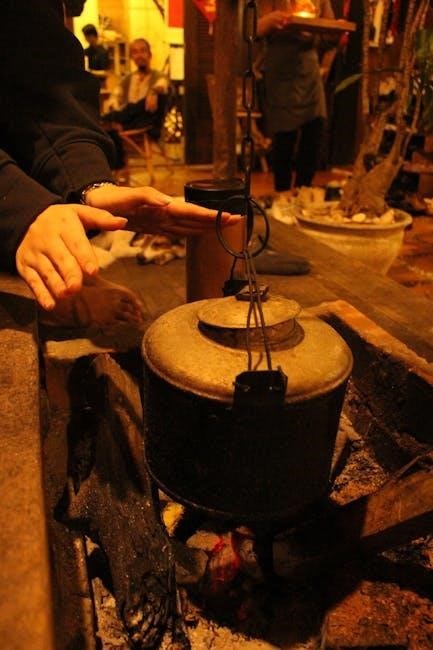
To start your Majestic gas fireplace, ensure the area is clear of flammable materials. Refer to your owner’s manual for specific instructions tailored to your model. Locate the ignition control, typically found near the base or behind the decorative front. Turn the gas supply knob to the “pilot” position and press the ignition button until the pilot light ignites. Once the pilot is lit, slowly turn the knob to the “on” position to activate the main burner. Adjust the flame height using the control knob as desired. For models with remote control, follow the remote’s instructions to ignite the fireplace. Always monitor the flame’s appearance and ensure it burns cleanly. If unsure, consult your manual or contact Majestic support. Routine maintenance, such as cleaning the glass and checking for blockages, will ensure optimal performance. Remember to always follow safety guidelines for a safe and enjoyable experience.

4.2 Routine Maintenance Tips

Regular maintenance is essential to ensure your Majestic gas fireplace operates safely and efficiently. Inspect the venting system annually for blockages or damage, and clean it as needed. Dust and debris can accumulate, so gently vacuum the interior and exterior surfaces. For glass doors, use a soft cloth and a mild glass cleaner to maintain clarity. Check the pilot light regularly to ensure it burns a steady blue flame. If the flame appears yellow or unstable, contact a professional. Always turn off the fireplace before performing any maintenance. Refer to your owner’s manual for specific instructions tailored to your model. Addressing minor issues promptly prevents larger problems from developing. Remember, proper upkeep extends the lifespan of your fireplace and ensures a safe, enjoyable experience. Schedule annual inspections by a qualified technician for optimal performance.

Troubleshooting Common Issues

Identify issues like ignition problems or error codes. Refer to your manual for solutions or contact Majestic support for professional assistance. Ensure safety and efficiency always.

5.1 Diagnosing Common Problems

Diagnosing issues with your Majestic fireplace starts with identifying symptoms like ignition failure, error codes, or uneven flames. Always refer to your user manual for specific guidance. If the fireplace doesn’t light, check the gas supply and igniter. For error codes, consult the manual’s troubleshooting section. Listen for unusual noises, as they may indicate worn or damaged parts. If you notice soot buildup, ensure proper venting and maintenance. Never attempt repairs without turning off the gas supply. If issues persist, contact a certified technician to avoid safety risks. Regular inspections can prevent many common problems. Always follow the manufacturer’s instructions for safe and effective troubleshooting. Remember, safety should never be compromised when addressing fireplace issues.

5.2 Resetting Your Majestic Fireplace

Resetting your Majestic fireplace is a straightforward process to restore functionality after minor issues. First, ensure the gas supply is turned off and allow the unit to cool. Locate the reset button, typically found near the control panel or behind the lower grille. Press and hold the button for 10-15 seconds until you hear a click. Release, then turn the gas supply back on. If the fireplace still doesn’t operate, check for error codes in your manual. Repeat the reset process if necessary. If issues persist, consult the troubleshooting guide or contact Majestic support. Always follow safety precautions and never force the reset button, as this could cause damage. Regular resets can help maintain optimal performance and safety.

Parts and Accessories

Majestic fireplaces offer genuine parts and accessories to enhance functionality. Use only approved components for safety and optimal performance, ensuring compliance with warranty terms and standards.

6.1 Identifying Genuine Majestic Parts

To ensure safety and performance, always use genuine Majestic parts. These components are designed to meet strict quality and safety standards, guaranteeing reliability and compliance with regulations. Genuine parts can be identified by their official Majestic branding and packaging, which includes specific logos and serial numbers; Avoid counterfeit products, as they may compromise safety and void your warranty. When purchasing parts, verify the supplier’s authenticity and look for certification labels; For assistance, refer to the Majestic fireplace user manual or contact authorized dealers. Genuine parts are essential for maintaining your fireplace’s efficiency and ensuring a hazard-free operation.

6.2 Optional Accessories for Enhanced Functionality

Enhance your Majestic fireplace experience with optional accessories designed to improve functionality and aesthetics. Glass doors are a popular choice, offering a sleek look while providing an extra layer of safety. Remote controls allow for convenient operation, enabling you to adjust settings without leaving your seat. Additionally, decorative fronts and trim kits can customize the appearance to match your home decor. For added ambiance, consider installing a blower kit to circulate warmth more efficiently. Always ensure that any accessory is approved by Majestic to maintain safety and warranty validity. Refer to your Majestic fireplace user manual for compatibility guidelines or contact customer support for recommendations. These accessories can elevate your fireplace’s performance and personalization, ensuring a tailored and enjoyable experience.

Regulatory Compliance

Majestic fireplaces are designed to meet CSA 2.26b-2004 standards, ensuring compliance with safety regulations and adherence to local building codes for reliable installation and operation.

7.1 Certification and Standards

Majestic fireplaces are rigorously tested to meet or exceed industry standards, ensuring safety and performance. They are certified according to CSA 2.26b-2004 and CGA 2.26b-2004 standards, which cover decorative gas appliances for installation in solid-fuel burning fireplaces. These certifications guarantee that the fireplaces comply with stringent safety and efficiency requirements. By adhering to these standards, Majestic fireplaces provide reliable performance and peace of mind for homeowners. Compliance with these regulations is a testament to the brand’s commitment to quality and safety, making Majestic fireplaces a trusted choice for those seeking a safe and efficient heating solution.

7.2 Adherence to Local Building Codes

Installing a Majestic fireplace requires strict adherence to local building codes and regulations. These codes vary by jurisdiction and dictate specific requirements for venting, clearance, and installation practices. Compliance ensures not only safety but also proper functionality of the fireplace. Homeowners must consult local authorities to understand the specific regulations applicable to their area. Proper permits and inspections are often necessary to guarantee that the installation meets all legal and safety standards. By following local building codes, homeowners can enjoy their Majestic fireplace with confidence, knowing it is safely and correctly installed. This adherence also helps prevent potential hazards and ensures the warranty remains valid. Always work with a qualified installer familiar with local regulations to ensure full compliance.

Warranty and Support

Your Majestic fireplace comes with a comprehensive warranty covering parts and labor for a specified period. Register your product to ensure full warranty benefits.

Contact Majestic customer support for assistance with warranty claims, troubleshooting, or general inquiries. Their dedicated team is available to help you enjoy your fireplace worry-free.

8.1 Understanding Your Warranty Coverage

Your Majestic fireplace warranty provides comprehensive coverage for parts and labor, ensuring protection against manufacturing defects. The warranty period varies depending on the model and components, typically ranging from one to five years.

Coverage includes repairs or replacements of defective parts, excluding normal wear and tear. For detailed terms, refer to your product’s warranty documentation or contact Majestic support. Proper installation and maintenance are required to maintain warranty validity. Keep your proof of purchase and registration for any warranty claims. This ensures your fireplace remains a reliable and enjoyable addition to your home, backed by Majestic’s commitment to quality and customer satisfaction.

8.2 Contacting Majestic Customer Support

For any inquiries or assistance with your Majestic fireplace, contact our customer support team. You can reach us via phone at 1-800-MAJESTIC or through email at support@majesticfireplaces.com. Our support specialists are dedicated to assisting you with installation, maintenance, or troubleshooting. Visit our official website at www.majesticfireplaces.com for additional resources, including FAQs and contact forms. When reaching out, have your fireplace model number and serial number ready to expedite the process. Our team is committed to providing the best support experience to ensure your satisfaction with your Majestic fireplace.

crosley record player user manual

Welcome to the Crosley Record Player User Manual. This guide provides essential information for setting up, operating, and maintaining your turntable. Learn about key features, safety guidelines, and troubleshooting tips to ensure optimal performance and longevity of your device.

1.1 Product Overview

The Crosley Record Player is a versatile and feature-rich device designed to enhance your vinyl listening experience. It offers Bluetooth connectivity, USB functionality, and built-in speakers for convenient playback. With adjustable pitch control, you can customize your listening experience. The turntable supports 33 1/3, 45, and 78 RPM speeds, ensuring compatibility with various record sizes, including 7″, 10″, and 12″ formats. Its sleek design and user-friendly interface make it a perfect addition to any home audio setup. Safety features include precautions against water exposure, emphasizing proper handling to maintain performance. This manual will guide you through setup, operation, and maintenance to ensure years of enjoyable use.

1.2 Safety Precautions

To ensure safe and optimal use of your Crosley Record Player, follow these guidelines. Avoid placing the turntable near water or exposing it to extreme temperatures. Keep the device away from direct sunlight and moisture to prevent damage. Never submerge the turntable in water or clean it with wet cloths, as this may cause electrical malfunctions. Handle the power cord with care, avoiding overloading circuits or using damaged cables. Always unplug the unit before cleaning or performing maintenance. Avoid touching the record grooves or the needle to prevent dust accumulation and damage. Store records in a cool, dry place to maintain their quality. Regularly inspect the tonearm and belt for wear. Read this manual thoroughly before operation to ensure proper handling and usage. Retain this manual for future reference.

System Components

The Crosley record player consists of external components like a turntable platter, slip mat, and tonearm, while internal parts include a motor, belt, and pitch control mechanism.

2.1 External Components

The Crosley record player features several external components designed for optimal performance. The turntable platter is the circular surface where records spin, ensuring stable playback. A slip mat is placed on top of the platter to protect records from scratches and provide cushioning. The tonearm, equipped with a cartridge and stylus, reads the grooves of the record, delivering high-quality audio. Additionally, the 45 RPM adapter is included for playing 7-inch records. External speakers or a headphone jack may also be connected for enhanced listening experiences. The power adapter is essential for powering the unit, and some models include a remote control for convenient operation. These components work together to provide a seamless and enjoyable vinyl listening experience.

2.2 Internal Parts

The internal components of the Crosley record player are crucial for its operation. The motor, located beneath the platter, powers the rotation of the turntable, ensuring consistent speed for record playback. A drive belt connects the motor to the platter, minimizing vibrations and noise. The main circuit board manages electrical connections, controlling functions like speed adjustment and USB or Bluetooth features. The cartridge and stylus, while externally visible, are internally connected to the tonearm mechanism, which reads record grooves for audio reproduction. Additionally, the counterweight on the tonearm balances its movement, ensuring proper tracking and preventing needle skips. These internal parts work together seamlessly to deliver high-quality sound and reliable performance. Regular maintenance of these components is essential for longevity and optimal functionality.

Installation and Setup

Welcome to the installation and setup section. Carefully unpack your Crosley record player, ensuring all accessories are included. Place the turntable on a stable, flat surface, away from direct sunlight and moisture. Connect the power supply and external components as described in the manual. Follow the step-by-step guide to ensure proper setup for optimal performance.

3.1 Unpacking and Accessories

Carefully unpack your Crosley record player to ensure no damage occurs. Verify all included accessories, such as the turntable, platter, slip mat, tonearm, and power adapter. Check for additional items like a 45 RPM adapter and any complementary cleaning tools. Ensure the packaging contains no missing components. Familiarize yourself with each part’s purpose before proceeding. Handle the turntable and accessories with care to avoid scratches or damage. Retain the original packaging and accessories for future reference or potential servicing. If any items are missing, contact Crosley Customer Service immediately. Properly organizing your accessories ensures a smooth setup process and optimal performance of your record player.

3.2 Placement and Environment

Place your Crosley record player on a stable, flat surface to ensure proper operation. Avoid positioning it near water or in humid environments to prevent damage. Keep the turntable away from direct sunlight and heat sources to maintain optimal performance. Ensure the area is free from vibrations or movement, as this could affect sound quality. Use a firm, non-slip surface to prevent accidental shifting. Position the turntable at least 6 inches away from any walls or obstructions for proper airflow. Maintain a clean and dust-free environment to protect the internal components. Avoid placing the turntable in areas prone to moisture or extreme temperatures, as this may damage the electronics or warping the records. Proper placement ensures longevity and optimal sound quality for your Crosley record player.

3.3 Connecting Power Supply

To power your Crosley record player, locate the DC power input on the back of the unit. Use the provided power adapter, ensuring it is securely connected to both the turntable and a nearby electrical outlet. Always plug the adapter into a grounded outlet to prevent electrical hazards. Avoid using damaged cords or adapters, as they may cause malfunctions or safety risks. Never submerge the power supply in water or expose it to excessive moisture. Before handling internal components, unplug the power cord to ensure your safety. Once connected, turn on the power switch, typically located on the front or side of the unit, to activate the turntable. Ensure the power supply matches the voltage requirements specified in the manual to avoid damage.

Operating the Turntable

Operating the Crosley turntable involves starting the motor, placing the record, and using the tonearm. Adjust speed as needed and refer to specific sections for details.

4.1 Basic Operation Steps

Start by powering on the turntable and selecting the appropriate record size and speed using the controls. Gently lift the tonearm and place it at the record’s edge. Ensure the record is clean and properly aligned. Once the record begins playing, adjust the volume if needed. For automatic models, the tonearm will return to its rest position after the record finishes. For manual models, lift the tonearm and turn off the power. Always handle the record by the edges to avoid fingerprints. Use the remote control for convenient operation if available. Refer to the speed and pitch control sections for fine-tuning playback. Proper handling ensures optimal performance and longevity of your Crosley turntable.

4.2 Speed and Pitch Control

The Crosley record player allows for precise speed and pitch adjustments to ensure optimal playback. Use the speed selector to choose between 33, 45, or 78 RPM, depending on the record size. The pitch control knob fine-tunes the playback speed, ideal for adjusting tempo or syncing tracks. To adjust, gently rotate the knob while monitoring the sound. For accurate playback, ensure the speed matches the record’s label specifications. Pitch control is particularly useful for DJs or vinyl enthusiasts who need precise tempo adjustments. Always refer to the manual for specific guidance on using these features effectively. Proper use of speed and pitch controls enhances your listening experience and preserves record quality.

4.3 Playing Records

To play records on your Crosley turntable, start by ensuring the power is turned on. Carefully lift the tonearm using the Tonearm Lever and gently place it on the record’s edge. Select the correct RPM (33, 45, or 78) based on the record’s size and speed. For automatic models, the tonearm will return to its rest position after playback. For manual models, use the Tonearm Lever to lift it once the record finishes. Always handle records by the edges to avoid fingerprints and scratches. Ensure the record is clean and free of dust for optimal sound quality. Refer to the manual for specific instructions on adjusting settings for different record formats. Proper handling and setup ensure a smooth and enjoyable listening experience.

4.4 Using USB and Bluetooth Features

Your Crosley record player offers convenient USB and Bluetooth connectivity for enhanced versatility. To use the USB feature, connect the turntable to your computer using the provided USB cable. Install the necessary software (often included) to digitize your vinyl records. For Bluetooth, ensure the turntable is in pairing mode, then connect your device (smartphone, speaker, or tablet) via Bluetooth settings. Once paired, you can stream audio wirelessly. Note that some models may require a PIN during pairing. Ensure your device is within range for optimal connection. Troubleshooting tips include resetting the Bluetooth connection or restarting the player. Always refer to your specific model’s manual for detailed instructions, as features may vary. This functionality allows you to modernize your vinyl experience while maintaining classic playback charm.

Maintenance and Care

Regularly clean the turntable platter, tonearm, and stylus to prevent dust buildup. Use a soft cloth and avoid harsh chemicals. Check the belt for wear and replace if necessary. Ensure the cartridge is properly aligned for optimal performance; Refer to the manual for detailed maintenance instructions to preserve your record player’s longevity and sound quality.

5.1 Cleaning the Turntable

Regular cleaning is essential to maintain your Crosley record player’s performance. Start by gently wiping the platter with a soft, dry cloth to remove dust and debris. For more thorough cleaning, use a mild soap solution on a damp cloth, ensuring no liquids seep into internal components. Avoid harsh chemicals or abrasive materials that could damage the finish or harm the equipment. Clean the tonearm and stylus with a specialized brush to remove dust. For stubborn grime, use a vinyl record cleaning solution and a microfiber cloth. Always handle the stylus carefully to prevent damage. Regular cleaning ensures optimal sound quality and extends the life of your turntable.

5.2 Troubleshooting Common Issues

If your Crosley record player experiences issues, start by checking the power supply and ensuring all connections are secure. If the turntable doesn’t spin, verify that the power button is functioning and the tonearm is not obstructed. For uneven playback, ensure the turntable is level and the record is clean. Static or distorted sound may result from a dirty stylus or improper record placement. Clean the stylus gently with a specialized brush and ensure records are free of dust. If issues persist, consult the user manual for detailed troubleshooting steps or contact Crosley customer support for assistance. Regular maintenance can prevent many common problems and ensure optimal performance.

5.3 Regular Maintenance Checks

Regular maintenance is crucial to ensure your Crosley record player performs optimally. Start by cleaning the turntable platter and slip mat with a soft cloth and mild detergent. Inspect the stylus for dust or debris and gently clean it with a specialized brush. Check the belt for wear and tear, and replace it if necessary. Ensure the platter is level and securely fastened. Lubricate the motor bearings periodically to maintain smooth operation. Additionally, verify that all electrical connections are secure and free from damage. Dust the internal components with compressed air to prevent buildup. For optimal sound quality, inspect the tonearm for proper alignment and balance. Refer to the user manual for specific maintenance schedules and guidelines to extend the lifespan of your record player.

Additional Features

Your Crosley record player includes built-in speakers, Bluetooth connectivity, and USB support for digital recording. It also features a remote control and compatibility with various accessories for enhanced functionality.

6.1 Built-in Speakers

The Crosley record player is equipped with high-quality, built-in speakers designed to deliver crisp and clear audio. These speakers provide an all-in-one solution for enjoying your vinyl records without the need for external sound systems. With balanced tone and adequate volume, they are perfect for casual listening sessions. The built-in speakers are optimized for both 33⅓ and 45 RPM records, ensuring compatibility with your entire collection. For enhanced sound quality, you can easily connect external speakers using the RCA output ports. This feature offers flexibility, allowing you to customize your listening experience according to your preferences.

6.2 Remote Control Functionality

The Crosley record player comes with a remote control, offering convenient operation from a distance. This feature allows you to control playback functions, adjust volume, and navigate tracks effortlessly. The remote is pre-programmed for seamless integration with your turntable, ensuring smooth operation. For additional devices like DVD players, the remote may require programming, as detailed in the manual. Battery installation is straightforward, and the remote’s intuitive design makes it user-friendly. Regularly check battery levels to maintain functionality. This feature enhances your listening experience, providing comfort and flexibility for music enthusiasts. The remote control adds a modern touch to the classic vinyl experience, making it easier to enjoy your records without moving from your seat.

6.3 Compatible Accessories

The Crosley record player supports a range of compatible accessories to enhance your listening experience. These include high-quality cleaning kits, designed to maintain your turntable’s performance by removing dust and debris. Additionally, replacement needles and styli are available to ensure optimal sound quality. Crosley also offers 45 RPM adapters for playing smaller records and slip mats to protect your records during playback. These accessories are specifically designed to work seamlessly with your Crosley turntable, ensuring compatibility and reliability. Regular use of these items will help preserve the longevity of your device and maintain its audio fidelity. For more details on available accessories, refer to the Crosley customer support resources or the product’s official website.

Technical Specifications

Explore the technical details of your Crosley record player, including dimensions, weight, supported record sizes, and power requirements, ensuring compatibility and proper setup for optimal performance.

7.1 Dimensions and Weight

Your Crosley record player is designed to fit seamlessly into your space. The unit measures approximately 12.2 x 10.8 x 6.3 inches and weighs around 12.1 pounds, making it compact yet sturdy. The dimensions ensure it can sit comfortably on most shelves or countertops without occupying excessive space. The weight provides stability, reducing vibration during operation. Note that dimensions may vary slightly depending on the specific model and finish. Always check the product packaging or manufacturer’s website for precise measurements to ensure proper placement in your home audio setup. This information is crucial for planning your space and ensuring the turntable operates efficiently in its intended environment.

7.2 Supported Record Sizes

Your Crosley record player is compatible with standard vinyl records in sizes of 7 inches, 10 inches, and 12 inches. It supports playing speeds of 33 1/3 RPM for LPs and 45 RPM for singles, ensuring versatility for your vinyl collection. The turntable comes equipped with a 45 RPM adapter to accommodate smaller records. Always verify the record size and speed before playback to ensure optimal performance. The player is designed to handle both vintage and modern vinyl formats, making it a versatile addition to your home audio system. Properly align the record size with the turntable’s capabilities to maintain sound quality and prevent damage to your records or the device.

7.3 Power Requirements

Your Crosley record player operates on standard household power, requiring a 120V AC, 60Hz power supply. It comes with a compatible power adapter that ensures safe and efficient operation. To avoid damage, use only the provided adapter or one with identical specifications. The turntable is designed for energy efficiency, consuming minimal power while delivering high-quality sound; Always plug the device into a grounded outlet to prevent electrical hazards. Avoid using the player near water or in humid environments, as this could compromise its functionality. For optimal performance, ensure the power cord is securely connected and free from damage. Refer to the manual or contact Crosley Customer Support for any power-related issues or concerns.

Appendix

This section includes warranty details, customer support contacts, and troubleshooting guides. Refer here for additional resources and information to assist with your Crosley record player experience.

8.1 Warranty Information

Your Crosley Record Player is backed by a limited warranty that covers manufacturing defects for a specified period. The warranty period typically starts from the date of purchase and varies depending on the model. To ensure coverage, register your product on the Crosley website within 30 days of purchase. The warranty does not cover damage caused by misuse or normal wear and tear. For warranty claims or inquiries, contact Crosley Customer Service at 1-888-CROSLEY or visit their official website. Keep your purchase receipt as proof of ownership, as it may be required for warranty validation.

8.2 Customer Support Contact

For any inquiries, technical assistance, or warranty-related issues, contact Crosley Customer Support. You can reach them by phone at 1-888-CROSLEY or visit their official website at www.crosleyradio.com for additional support resources. For email inquiries, use the contact form available on their website. Ensure to provide your product model number and a detailed description of your issue for faster assistance. Customer service representatives are available to help with troubleshooting, repair requests, or general questions about your record player. Retain your purchase receipt and warranty documentation, as they may be required for support. For international customers, refer to the website for region-specific contact information.

carrier comfort zone ii manual

The Carrier Comfort Zone II Manual provides a comprehensive guide to understanding and utilizing the advanced zoning system, designed for 2, 4, or 8 zones, ensuring energy efficiency and customized comfort control for optimal indoor climate management.

1.1 Overview of the Comfort Zone II System

The Comfort Zone II System is a advanced zoning solution designed to control temperatures and humidity in up to 8 distinct areas. It offers customizable comfort, energy efficiency, and seamless integration with heating and cooling systems. The system includes a central interface, equipment controller, and remote sensors, enabling precise control over individual zones. Its programmable scheduling and energy-saving features make it ideal for both residential and commercial applications, ensuring optimal indoor climate management.

1.2 Purpose of the Manual

The purpose of the Carrier Comfort Zone II Manual is to provide users with a detailed guide for installing, operating, and maintaining the Comfort Zone II System. It serves as a comprehensive resource, offering step-by-step instructions, troubleshooting tips, and technical specifications. The manual ensures that users can maximize the system’s potential, customize settings, and resolve common issues, thereby optimizing comfort and energy efficiency in their homes or businesses effectively.

1.3 Target Audience

The Carrier Comfort Zone II Manual is designed for homeowners, business owners, installers, and technicians. It provides essential information for setting up, operating, and maintaining the system. Whether customizing comfort settings or troubleshooting issues, this manual serves as a vital resource for all users, ensuring they can maximize the system’s energy efficiency and performance to meet their specific needs effectively.

Key Features of the Comfort Zone II System

The Comfort Zone II System offers advanced zoning capabilities for 2, 4, or 8 zones, ensuring energy efficiency and customized comfort. It features programmable thermostats, humidity management, and smart sensor integration, allowing users to optimize their indoor climate while saving energy and enhancing overall comfort.

2.1 Zoning Capabilities (2, 4, or 8 Zones)

The Comfort Zone II System offers flexible zoning capabilities, supporting 2, 4, or 8 zones, allowing precise temperature control in each area. This feature enables users to customize comfort levels, reduce energy waste, and optimize system performance. Each zone operates independently, ensuring tailored climate control for different spaces within a home or business, enhancing overall efficiency and user satisfaction.

2.2 Energy Efficiency and Customized Comfort

The Comfort Zone II System maximizes energy efficiency by allowing precise temperature control in specific zones, reducing unnecessary heating or cooling. Customized comfort is achieved through tailored settings for each zone, ensuring optimal conditions. The system adapts to your home’s needs, learning preferences to balance energy savings and comfort. Smart sensors and humidity management further enhance efficiency, making it a versatile solution for modern energy-conscious homes.

2.3 Programmable Thermostat Functionality

The programmable thermostat in the Comfort Zone II System offers flexible scheduling, allowing users to set temperature preferences up to seven days in advance. This feature ensures consistent comfort and energy savings by automating temperature adjustments. Customizable settings enable precise control, while temporary hold and override options provide flexibility for unexpected changes. The thermostat’s intuitive interface simplifies programming, making it easy to optimize your home’s climate efficiently.

2.4 Humidity Control and Management

The Comfort Zone II System includes advanced humidity control, ensuring optimal indoor air quality. It integrates seamlessly with the programmable thermostat, allowing users to set specific humidity levels for each zone. This feature prevents excessive moisture, reducing mold growth and dust mites. By managing humidity alongside temperature, the system enhances comfort and energy efficiency, providing a healthier living environment year-round. The humidity sensors and dampers work together to maintain balanced air conditions.

Installation Guide

The guide provides detailed instructions for installing the Comfort Zone II System, including pre-installation requirements, wiring diagrams, and post-installation checks to ensure proper system functionality and safety.

3.1 Pre-Installation Requirements

Before installing the Comfort Zone II System, ensure compatibility with existing HVAC equipment and verify space requirements. Conduct a site survey to identify zoning needs and optimal sensor placement. Gather all necessary tools, materials, and documentation, including wiring diagrams and system specifications. Ensure power is disconnected during installation to maintain safety and prevent electrical hazards.

3.2 Step-by-Step Installation Process

Begin by mounting the control interface in a central location, ensuring easy access. Connect the outdoor temperature sensor and remote sensors to the system. Follow the wiring diagram to link the equipment controller to the HVAC system. Connect zone dampers and thermostats, ensuring proper wiring for power and communication. Refer to the manual for specific wiring configurations and safety guidelines to ensure a successful installation.

3.3 Wiring Diagrams and Connections

Refer to the provided wiring diagrams for precise connections between the control interface, equipment controller, and zone dampers. Ensure all terminals are securely connected, and power wiring is correctly routed. Verify communication cables are properly linked to enable system coordination. Double-check all connections to avoid malfunctions and ensure compliance with safety standards outlined in the manual.

3.4 Post-Installation Checks

After installation, perform a thorough system test to ensure all components function correctly. Verify zone operations, thermostat settings, and communication between devices. Check damper functionality and validate temperature and humidity controls. Review error codes and ensure electrical connections are secure. Confirm system operation aligns with manual guidelines to optimize performance and energy efficiency. Address any issues promptly to ensure reliable system operation.

Programming and Operation

The Carrier Comfort Zone II allows users to program temperature schedules, manage humidity levels, and utilize temporary hold features for personalized comfort and energy efficiency.

4.1 Understanding the Thermostat Interface

The Carrier Comfort Zone II thermostat features an intuitive interface with a backlit display, touch-sensitive buttons, and clear status indicators. Users can easily navigate through menus to adjust temperatures, scheduling, and humidity settings. The interface provides real-time feedback, ensuring precise control over zoning preferences. Additional features include a help menu for guidance and system status updates, making it user-friendly for both homeowners and businesses to manage their indoor climate efficiently.

4.2 Setting Up Temperature Schedules

The Carrier Comfort Zone II allows users to create customized temperature schedules for up to 7 days, ensuring optimal comfort and energy efficiency. Programmable settings enable precise temperature control during different times of the day, aligning with your lifestyle. The system also features energy-saving modes and adaptive recovery, automatically adjusting temperatures before scheduled times to maintain consistent comfort while minimizing energy usage across all zones.

4.3 Managing Humidity Levels

The Carrier Comfort Zone II system includes advanced humidity control features, allowing users to set and maintain optimal moisture levels across all zones. Customizable humidity settings ensure consistent comfort while preventing mold growth and excess moisture. The system integrates seamlessly with programmable schedules, adjusting humidity levels automatically based on time and temperature preferences for enhanced energy efficiency and indoor air quality management.

4.4 Temporary Hold and Override Features

The Carrier Comfort Zone II system offers Temporary Hold and Override Features, allowing users to make immediate adjustments to temperature and humidity settings without altering programmed schedules. This feature is ideal for unexpected changes in occupancy or comfort needs. Temporary adjustments are easy to implement and revert back to the original schedule automatically, ensuring energy efficiency and maintaining customized comfort levels seamlessly.

Maintenance and Troubleshooting

Regular maintenance ensures optimal performance of the Carrier Comfort Zone II system. Check air filters, sensors, and wiring. Troubleshoot common issues like uneven temperatures or system errors by consulting the manual or contacting support for assistance.

5.1 Routine Maintenance Checks

Regular maintenance is essential for the Carrier Comfort Zone II system. Clean or replace air filters, inspect sensors, and check wiring connections. Verify humidity levels and ensure dampers function properly. Schedule annual professional inspections to maintain efficiency and prevent issues. Refer to the manual for detailed procedures and guidelines to ensure optimal performance and longevity of the system.

These checks help prevent malfunctions and ensure consistent comfort control.

5.2 Troubleshooting Common Issues

Identify issues by checking sensors, wiring, and system responses. Common problems include faulty temperature readings, uneven zone performance, or unresponsive controls. Refer to the manual for error codes and solutions. Resetting the system or replacing sensors may resolve issues. Always ensure proper connections and power supply. Regular inspections can help prevent recurring problems and maintain system efficiency.

Consult the manual for detailed troubleshooting steps.

5.3 Error Codes and Solutions

The Carrier Comfort Zone II system displays error codes to indicate specific issues. Common codes include E1 for sensor malfunctions, E2 for communication errors, and E3 for damper issues. Refer to the manual for code meanings and troubleshooting steps. Solutions may involve resetting the system, replacing sensors, or checking wiring connections. Always consult the manual for detailed repair instructions to resolve errors effectively.

Ensure proper system operation by addressing codes promptly.

5.4 Resetting the System

To reset the Carrier Comfort Zone II system, turn off power at the circuit breaker for 30 seconds. Turn power back on and allow the system to restart. This process clears temporary glitches and restores default settings. If issues persist, refer to the manual for advanced troubleshooting or contact a certified technician. Resetting ensures optimal performance and resolves minor operational errors effectively.

Always power cycle the system before attempting further repairs.

Advanced Features and Integration

The Carrier Comfort Zone II offers advanced integration with smart home systems, enabling remote monitoring and control. Smart sensors optimize performance, while energy reporting tracks savings and system updates ensure peak efficiency, enhancing overall functionality and user experience seamlessly.

6.1 Smart Sensors and Remote Monitoring

The Carrier Comfort Zone II system integrates seamlessly with smart sensors, allowing users to monitor and adjust temperatures, humidity, and zone settings remotely. These sensors enhance precision and convenience, ensuring optimal comfort levels. Remote monitoring capabilities enable real-time adjustments via mobile devices, making it easier to manage energy usage and maintain desired indoor conditions efficiently.

6.2 Compatibility with Smart Home Systems

The Carrier Comfort Zone II system is designed to integrate seamlessly with popular smart home platforms, such as Google Nest and Amazon Alexa. This compatibility allows users to control their zoning system alongside other smart devices, enabling voice commands and centralized home management. The integration enhances convenience, offering a unified smart home experience while maintaining precise temperature and humidity control across all zones.

6.3 Energy Reporting and Savings Tracking

The Carrier Comfort Zone II system offers advanced energy reporting and savings tracking features. Users can access detailed reports on energy consumption patterns, allowing for informed decisions to optimize efficiency. The system also provides insights into potential savings by adjusting temperature settings and humidity levels. These tools empower homeowners to reduce energy waste and lower utility bills while maintaining personalized comfort levels throughout their space.

6.4 System Upgrades and Updates

The Carrier Comfort Zone II system supports seamless upgrades and updates to enhance performance and compatibility. Users can easily update software and integrate new features, ensuring optimal functionality. The system allows for remote updates and compatibility with the latest smart home technologies, maintaining its efficiency and adaptability over time. Regular updates ensure the system remains current with technological advancements, providing long-term reliability and improved energy management capabilities.

Safety Considerations

The Carrier Comfort Zone II system requires adherence to electrical safety guidelines to prevent hazards. Always follow installation and operational instructions to ensure safe usage and avoid potential risks.

7.1 General Safety Precautions

Always follow the Carrier Comfort Zone II manual guidelines to ensure safe operation. Avoid exposing the system to water or extreme temperatures. Keep flammable materials away and ensure proper ventilation. Before performing any maintenance, disconnect power to prevent electrical shocks. Adhere to all safety warnings and precautions outlined in the manual to maintain system integrity and user safety.

7.2 Electrical Safety Guidelines

Follow the Carrier Comfort Zone II manual for electrical safety. Ensure all wiring matches system specifications and is installed by a licensed technician. Avoid overloading circuits and keep wires away from heat sources. Use properly rated fuses and circuit breakers. Always disconnect power before servicing to prevent shocks or component damage, adhering to local electrical codes for a safe installation and operation.

7.3 Emergency Shutdown Procedures

In case of an emergency, refer to the Carrier Comfort Zone II manual for shutdown procedures. Immediately disconnect power at the circuit breaker or switch. Use the emergency shut-off switch if available. Ensure all components stop operating to prevent damage or hazards. Always follow the manual’s guidelines to safely deactivate the system and consult a professional if unsure. This ensures safety and prevents potential risks during unexpected situations.

Technical Specifications

The Carrier Comfort Zone II system supports up to 8 zones, with compatibility for various HVAC systems. It operates on 24V power and requires specific dimensional clearances for installation. The system is designed for efficient performance across a wide range of environmental conditions, ensuring reliable control and operation in diverse settings. Always refer to the manual for exact measurements and electrical requirements.

8.1 System Compatibility

The Carrier Comfort Zone II system is compatible with a wide range of HVAC equipment, including heat pumps, dual-fuel systems, and traditional heating and cooling units. It supports integration with smart home systems and can be paired with optional smart sensors for enhanced functionality. The system works seamlessly with 2, 4, or 8-zone configurations, making it versatile for both residential and light commercial applications. Proper installation ensures optimal performance across all compatible systems.

8.2 Dimensional and Weight Requirements

The Carrier Comfort Zone II system components are designed to fit standard installation spaces. The main unit measures 3.5 inches in height, 5.75 inches in width, and 1.375 inches in depth, ensuring compatibility with most mounting configurations. The system’s weight is approximately 3.5 pounds, making it lightweight and easy to handle during installation. These dimensions and weight specifications ensure seamless integration into various residential and commercial settings without compromising performance or functionality.

8.3 Power Requirements

The Carrier Comfort Zone II system operates on a standard 24V AC power supply, ensuring compatibility with most residential and commercial electrical systems. It is designed to consume minimal power while maintaining high efficiency. The system does not require additional power supplies for basic functionality, making it a cost-effective solution. Proper adherence to these power requirements ensures optimal performance, safety, and system longevity.

8.4 Environmental Operating Range

The Carrier Comfort Zone II system is designed to operate effectively in a wide range of environmental conditions. It functions optimally in temperatures between 32°F and 90°F (0°C to 32°C) and maintains performance in humid environments, typically below 80% relative humidity. These specifications ensure reliable operation across various climates and indoor settings, adhering to the manual’s guidelines for optimal performance and system longevity.

Warranty and Support

The Carrier Comfort Zone II system is backed by a comprehensive manufacturer warranty, ensuring coverage for parts and labor. Dedicated customer support is available for troubleshooting, while online resources provide additional guidance and documentation to assist users in maintaining optimal system performance and resolving issues promptly. Proper registration is required to validate warranty terms.

9.1 Manufacturer Warranty Details

The Carrier Comfort Zone II system offers a comprehensive manufacturer warranty, providing coverage for parts and labor under specific conditions. The standard warranty typically includes a 5-year limited warranty on parts and a 1-year limited warranty on labor when installed by a certified technician. Extended warranty options may be available, offering enhanced protection for up to 10 years. Proper registration within 90 days of installation is required to activate warranty benefits. Additionally, the system must be maintained according to the manufacturer’s guidelines to ensure warranty validity. Any unauthorized modifications or improper installations may void the warranty. It is essential to review the warranty terms and conditions provided in the manual or on Carrier’s official website to understand the full scope of coverage and any applicable restrictions. By adhering to these requirements, users can enjoy peace of mind with reliable protection for their investment in the Comfort Zone II system.

9.2 Customer Support Contact Information

Carrier provides dedicated customer support for the Comfort Zone II system. Visit their official website at www.carrier.com for detailed contact information. You can reach their support team at 1-800-CARRIER for technical assistance, troubleshooting, or general inquiries; Support is available Monday through Friday, 8 AM to 6 PM EST. For efficient service, ensure to have your system’s model number ready when contacting support.

9.3 Online Resources and Documentation

Carrier offers extensive online resources for the Comfort Zone II system. Visit www.carrier.com to access PDF manuals, installation guides, and troubleshooting tips. Additionally, the Carrier website provides video tutorials, FAQs, and software updates to ensure optimal system performance. Users can also download the Comfort Zone II user manual directly from the site, available in multiple languages for global accessibility and convenience.

The Carrier Comfort Zone II Manual concludes by summarizing the system’s key benefits, including energy efficiency, zoning capabilities, and programmable features, ensuring optimal performance and comfort control for users.

10.1 Summary of Key Benefits

The Carrier Comfort Zone II system offers enhanced zoning capabilities, energy efficiency, and programmable features for customized comfort. It supports up to 8 zones, allowing independent temperature control in different areas, reducing energy waste. The system also includes humidity management and smart home compatibility, ensuring optimal performance and convenience. These features make it a comprehensive solution for modern heating and cooling needs, providing both comfort and energy savings.

10.2 Final Tips for Optimal Performance

For optimal performance, ensure routine maintenance, such as cleaning filters and checking wiring connections. Program temperature schedules to align with your daily routine and adjust humidity levels seasonally. Regularly update the system software and verify sensor accuracy. Address any error codes promptly and consider professional calibration for precise control. These practices will maximize efficiency, comfort, and system longevity, ensuring your Carrier Comfort Zone II operates at its best.

jlab sport earbuds manual

Welcome to the JLab Sport Earbuds manual! This guide provides essential information to help you understand and maximize the features of your earbuds, ensuring optimal performance and longevity.

Overview of JLab Sport Earbuds

The JLab Sport Earbuds are designed for active lifestyles, offering a perfect blend of comfort, durability, and high-quality sound. These wireless earbuds feature sweat and water resistance, making them ideal for workouts and outdoor activities. With their lightweight design and secure fit, they stay in place during intense movements. The earbuds support advanced audio features like EQ settings and active noise cancellation, providing an immersive listening experience. Battery life is impressive, offering up to 52 hours of playtime, or 42 hours with ANC enabled. Equipped with intuitive touch controls and seamless Bluetooth connectivity, these earbuds are built to keep up with your dynamic routine.

Importance of the Manual

The JLab Sport Earbuds manual is a crucial resource for users to unlock the full potential of their device. It provides detailed instructions on pairing, charging, and troubleshooting, ensuring seamless operation. The manual also highlights key features like EQ settings, active noise cancellation, and water resistance, helping users customize their experience. By following the guidelines, users can maintain battery health and prevent damage, extending the earbuds’ lifespan. Additionally, the manual offers insights into resolving common issues, such as connection problems or audio discrepancies, ensuring uninterrupted enjoyment. Whether you’re a new or experienced user, this guide is essential for maximizing functionality and satisfaction.

Design and Build Quality

The JLab Sport Earbuds feature a sleek, durable design with sweat and water resistance, perfect for active use. The charging case is compact and lightweight, ensuring portability.

Key Features of JLab Sport Earbuds

The JLab Sport Earbuds are designed with cutting-edge features for a seamless listening experience. They offer touch sensors for intuitive control, allowing users to manage music, calls, and voice assistants with ease. Equipped with advanced EQ settings, these earbuds deliver tailored sound quality to suit different preferences. The inclusion of active noise cancellation (ANC) ensures an immersive audio experience by minimizing ambient noise. With a focus on durability, they are sweat and water-resistant, making them ideal for workouts and outdoor activities. Additionally, the earbuds provide extended battery life, with up to 52 hours of playtime, and rapid charging capabilities for quick power-ups. These features combine to make the JLab Sport Earbuds a versatile and reliable choice for everyday use.

Water and Sweat Resistance

The JLab Sport Earbuds are designed to withstand tough workouts and outdoor activities, featuring water and sweat resistance to ensure reliability in various conditions. With an IP55 rating, they are protected against dust and moisture, making them ideal for fitness enthusiasts. The earbuds are built to endure sweat and accidental splashes, providing durability during intense exercises. However, it’s important to note that the charging case is not water-resistant, so care should be taken to keep it dry. Regular cleaning is recommended to maintain performance and prevent damage from sweat buildup. This feature enhances the earbuds’ versatility, allowing users to enjoy uninterrupted audio during workouts or in rainy environments. Proper maintenance ensures long-term functionality and sound quality.

Features and Specifications

The JLab Sport Earbuds offer premium sound quality, long battery life, and robust Bluetooth connectivity. They feature customizable EQ settings, touch controls, and water resistance for active lifestyles.

Sound Quality and EQ Settings

The JLab Sport Earbuds deliver crystal-clear sound with deep bass and balanced highs, ensuring an immersive listening experience. Users can customize their audio preferences with multiple EQ settings, such as Signature, Balanced, and Bass Boost modes, directly through the JLab Audio app. This feature allows for tailored sound that suits various music genres or personal preferences. The earbuds also support high-quality audio codecs, enhancing sound fidelity. Whether you’re enjoying music, podcasts, or calls, the sport earbuds provide clear and distortion-free audio. These customizable options make the JLab Sport Earbuds versatile for different listening needs and environments, ensuring optimal sound quality at all times.

Battery Life and Charging Times

The JLab Sport Earbuds offer impressive battery life, delivering up to 52 hours of playtime on a single charge. With active noise cancellation enabled, the battery life is reduced to 42 hours. The earbuds charge quickly, requiring approximately 2 hours for a full charge. A quick 15-minute charge provides up to 2 hours of playback, making them ideal for on-the-go use. The charging case supports wireless charging and stores enough power for up to 5 additional charges, extending total playtime to 260 hours. This long-lasting battery ensures uninterrupted listening sessions, whether you’re working out, traveling, or enjoying your favorite tracks.

Active Noise Cancellation (ANC)

The JLab Sport Earbuds feature advanced Active Noise Cancellation (ANC), designed to immerse you in pure sound by blocking out ambient noise. This technology is perfect for workouts, commutes, or focus-intensive tasks. ANC can be toggled on or off with a simple tap on the touch sensors, allowing you to switch between immersive sound and environmental awareness. The earbuds use dual microphones to detect and cancel external noise effectively, ensuring a distraction-free listening experience. With ANC enabled, the battery life is optimized to provide up to 42 hours of continuous playback, making these earbuds a versatile choice for everyday use. This feature enhances sound quality and user convenience, making it a standout attribute of the JLab Sport Earbuds.

Charging and Battery Management

Efficiently manage your JLab Sport Earbuds’ battery life by following proper charging practices. The charging case provides multiple charges on the go, ensuring uninterrupted listening. Always charge via the provided USB cable and avoid overcharging to maintain battery health. Store the earbuds in the case when not in use. Regularly clean the charging ports to prevent connectivity issues. Monitor battery levels using indicator lights and recharge when necessary. Proper care extends the lifespan of your earbuds, keeping them ready for your next adventure. This section guides you to optimize charging and maintain peak performance.

How to Charge the Earbuds

To charge your JLab Sport Earbuds, place them in the charging case, ensuring they align with the internal connectors. Connect the case to a USB port using the provided cable. The earbuds will automatically begin charging, with LED indicators showing the charging status. A full charge typically takes about 2-3 hours, providing up to 10 hours of playtime. Avoid overcharging, as it may affect battery longevity. When charging, keep the case away from moisture and extreme temperatures. Always use the original cable for optimal charging performance. Proper charging habits ensure your earbuds remain ready for use, delivering consistent audio quality and reliable battery life.

Charging Case and Battery Life

The JLab Sport Earbuds come with a compact charging case that provides multiple charges on the go. The case itself has a built-in battery, offering up to 4-5 full charges for the earbuds. With a fully charged case, you can enjoy up to 52 hours of total playtime, depending on usage and settings like ANC. The case charges via USB-C, reaching full power in about 2-3 hours. The earbuds themselves hold up to 10 hours of battery life per charge. The case features LED indicators to show its charge status, ensuring you never run out of power unexpectedly. This combination of portability and extended battery life makes the JLab Sport Earbuds ideal for long workouts, travel, or daily use.

Best Practices for Battery Health

To maintain the battery health of your JLab Sport Earbuds, follow these guidelines. Avoid extreme temperatures and keep the earbuds dry. Charge the case and earbuds regularly but avoid overcharging—ideally, unplug once fully charged. Store the earbuds in the case when not in use to prevent drained batteries. Clean the charging ports occasionally to ensure proper connection. For long-term storage, charge the earbuds to about 50% before storing. Replace the earbuds in the case correctly to ensure proper charging. By adhering to these practices, you can extend the lifespan of your earbuds’ battery and ensure consistent performance over time. Proper care will keep your JLab Sport Earbuds functioning optimally.

Pairing and Connectivity

Pair your JLab Sport Earbuds by removing them from the case and selecting them in your device’s Bluetooth settings. A blinking light indicates pairing mode is active.

Bluetooth Pairing Process

To pair your JLab Sport Earbuds, start by enabling Bluetooth on your device. Remove the earbuds from the charging case, and they will automatically enter pairing mode, indicated by a blinking light. Open your device’s Bluetooth settings and select “JLab Sport” from the list of available devices. Once connected, you’ll hear a voice prompt or see a solid light to confirm the connection. For subsequent use, the earbuds will auto-connect to your device when removed from the case. If pairing issues occur, reset the earbuds by tapping one earbud seven times while in the case. This ensures a fresh connection and resolves most Bluetooth-related problems.

Troubleshooting Connection Issues

If your JLab Sport Earbuds experience connection issues, start by resetting them. Place the earbuds in the charging case and forget the “JLab Sport” device from your Bluetooth settings; Next, quick-tap one earbud seven times while it’s in the case to reset it. Remove the earbuds and attempt pairing again. Ensure your device’s Bluetooth is enabled and that the earbuds are not connected to another device. If problems persist, restart your device and charge the earbuds for at least 30 minutes. These steps should resolve common connectivity problems and ensure a stable Bluetooth connection for uninterrupted use.

Resetting the Earbuds

Resetting your JLab Sport Earbuds is a simple process to resolve connectivity issues or prepare them for a new device. Start by placing the earbuds in the charging case. Open your device’s Bluetooth settings and forget the “JLab Sport” connection. Next, locate one of the earbuds in the case and perform a quick tap seven times on it. This action will reset the earbuds to their factory settings. Once reset, remove the earbuds from the case, and they will automatically enter pairing mode. Ensure your device’s Bluetooth is enabled to reconnect. Resetting ensures a clean connection and resolves common pairing or disconnection problems.

Controls and Functionality

The JLab Sport Earbuds feature intuitive touch sensors for seamless control over music, calls, and voice assistants. Use taps or holds to play/pause, adjust volume, or switch tracks;

Using Touch Sensors

The JLab Sport Earbuds feature intuitive touch sensors for easy control. To use them, gently tap or hold the sensors on either earbud. A single tap plays or pauses music, while a double tap skips to the next track. To adjust volume, tap and hold the left earbud to decrease volume or the right earbud to increase it. For calls, a single tap answers or ends a call, while a double tap rejects an incoming call. You can also activate voice assistants like Siri or Google Assistant by tapping and holding either earbud. Ensure your fingers make contact with the sensor for accurate response. Regularly clean the sensors to maintain functionality. Resetting the earbuds via touch sensors can resolve connectivity issues. Always refer to the manual for updated gesture controls.

Basic Controls for Music and Calls

The JLab Sport Earbuds offer straightforward controls for managing music and calls. To play or pause music, simply tap either earbud once. Skip to the next track by double-tapping the right earbud or the previous track by double-tapping the left. For volume control, tap and hold the right earbud to increase volume or the left to decrease it. For calls, a single tap answers or ends a call, while a double tap rejects an incoming call. Ensure your touch gestures are firm yet gentle for accurate response. Properly cleaning the sensors can enhance control accuracy. These intuitive controls allow seamless music and call management without needing your device.

Customizing Sound Settings

The JLab Sport Earbuds allow you to tailor your audio experience with customizable sound settings. Through the JLab app, you can adjust EQ settings, choosing from predefined options like Signature, Balanced, or Bass Boost to suit your preferences. Additionally, the earbuds feature touch sensors that enable you to cycle through different audio modes, such as ANC on, ANC off, or ambient sound mode. This level of customization ensures you can optimize sound quality for music, calls, or workouts. By exploring these features, you can enhance your listening experience and make the most of your earbuds’ advanced audio capabilities. Proper customization can significantly improve sound clarity and comfort during extended use.

Care and Maintenance

Regularly clean your JLab Sport Earbuds with a soft cloth and avoid exposing them to harsh chemicals or extreme temperatures. Store them properly in the charging case to maintain functionality and extend lifespan.

Cleaning the Earbuds

To maintain your JLab Sport Earbuds’ performance and hygiene, clean them regularly using a soft, dry cloth. Gently wipe away sweat, dirt, or earwax from the surfaces. For stubborn marks, dampen the cloth slightly with water, but avoid using harsh chemicals or submerging the earbuds in liquids. Pay special attention to the touch sensors and sound ports, as debris can affect functionality. For the charging case, use a soft cloth to remove dust or debris from the interior and exterior. Regular cleaning ensures optimal sound quality and prevents damage. Avoid using abrasive materials that might scratch the surfaces. Cleaning your earbuds and case regularly will extend their lifespan and keep them functioning at their best.

Storing the Earbuds Properly

Proper storage is crucial to maintain the performance and longevity of your JLab Sport Earbuds. Always store the earbuds in their charging case when not in use to protect them from dust and physical damage. Ensure the case is dry and free from debris before placing the earbuds inside. Avoid storing the earbuds in tight spaces or extreme temperatures, as this could warp or damage the components. For extended storage, charge the earbuds to about 50% to maintain battery health. Keep the case away from direct sunlight and moisture to prevent degradation. Proper storage habits will help preserve the sound quality, water resistance, and overall functionality of your earbuds.

Avoiding Damage

To ensure your JLab Sport Earbuds remain in optimal condition, avoid exposing them to unnecessary stress or harmful environments. Refrain from bending or twisting the earbuds excessively, as this could damage the internal components. Avoid submerging the earbuds in water beyond their IP rating, as this may compromise their water resistance. Clean the earbuds regularly with a soft cloth to remove dirt and earwax, which can affect sound quality and fit. Avoid using harsh chemicals or abrasive materials that might scratch the surfaces. Additionally, prevent the charging case from being crushed or dropped, as this could harm the internal charging circuitry. By taking these precautions, you can extend the lifespan and maintain the performance of your earbuds.

Warranty and Support

The JLab Sport Earbuds come with a one-year limited warranty, offering protection against manufacturing defects. For support, visit the official JLab website or contact their customer service team for assistance with troubleshooting, repairs, or general inquiries.

Understanding the Warranty

The JLab Sport Earbuds are backed by a one-year limited warranty, covering manufacturing defects in materials and workmanship. This warranty ensures your earbuds are free from defects under normal use. Damage caused by misuse, accidents, or unauthorized modifications is not covered. To claim warranty benefits, contact JLab support with proof of purchase. The warranty period begins from the original purchase date. JLab also offers dedicated customer service to address any concerns or issues. For more details, visit the official JLab website or refer to the warranty section in your manual. This support ensures your earbuds remain reliable and perform optimally throughout their lifespan.

Contacting JLab Support

For any inquiries, troubleshooting, or warranty claims, JLab provides comprehensive support options. Visit their official website and navigate to the support section, where you can find detailed FAQs, user manuals, and contact forms. If you need direct assistance, email support@jlabaudio.com or call their customer service team during business hours. Additionally, JLab’s social media channels are available for quick responses. Ensure to have your earbuds’ serial number and purchase details ready for efficient service. JLab’s dedicated team is committed to resolving your issues promptly, ensuring a seamless experience with your Sport Earbuds.

Downloading the Full Manual

To access the complete manual for your JLab Sport Earbuds, visit the official JLab website. Navigate to the Support section, where you’ll find a dedicated page for downloads. Look for the JLab Sport Earbuds manual or search for your specific model, such as the JBuds Air Sport or Epic Sport ANC. Click the download link to obtain the PDF version, which includes detailed instructions, troubleshooting guides, and specifications. This manual is essential for understanding advanced features and ensuring proper usage. For additional resources, explore the FAQs or product support videos available on the same page.

The JLab Sport Earbuds manual provides a comprehensive guide to unlocking their full potential. Follow the instructions to ensure optimal performance and an enhanced listening experience.

Final Tips for Optimal Use

For the best experience with your JLab Sport Earbuds, ensure a proper fit by trying different ear tips and secure placement. Regularly clean the earbuds to maintain sound quality and prevent damage. Keep the charging case topped up to avoid low battery situations. When pairing, reset the earbuds if connectivity issues arise. Customize your sound settings through the JLab app for a personalized listening experience. Store the earbuds in the case when not in use to protect them from dust and moisture. By following these tips, you’ll enjoy enhanced performance, longer battery life, and a more enjoyable listening experience with your JLab Sport Earbuds.

Exploring Additional Features

The JLab Sport Earbuds offer a range of advanced features to enhance your listening experience. Explore the customizable EQ settings through the JLab app, allowing you to tailor the sound to your preferences. Take advantage of the touch sensors to control music playback, answer calls, or activate voice assistants with ease. For those who prioritize sound quality, the earbuds support multiple audio modes, including balanced, bass boost, or treble-friendly settings. Additionally, the Active Noise Cancellation (ANC) feature helps immerse you in your music or podcasts by minimizing ambient noise. By exploring these features, you can unlock the full potential of your JLab Sport Earbuds and enjoy a personalized audio experience.

kenmore refrigerator model 111.730 manual

Welcome to the Kenmore Refrigerator Model 111.730 Manual, your comprehensive guide to understanding and maintaining your appliance. This manual provides detailed instructions for optimal performance and care.

Overview of the Manual

The Kenmore Refrigerator Model 111.730 Manual is a detailed guide designed to help users understand and maintain their appliance effectively. It covers installation, operation, and maintenance, as well as troubleshooting common issues. The manual also includes safety precautions, warranty information, and parts identification. Available in PDF format, it can be downloaded from Kenmore’s official website or other trusted sources, ensuring easy access to essential information for optimal performance and longevity of the refrigerator.

Importance of Reading the Manual

Reading the Kenmore Refrigerator Model 111.730 Manual is essential for proper installation, operation, and maintenance of your appliance. It provides critical safety guidelines, troubleshooting tips, and warranty details. By understanding the manual, you can optimize performance, prevent issues, and extend the lifespan of your refrigerator. Additionally, it ensures compliance with manufacturer recommendations, helping you make the most of your investment and maintain efficiency.

Key Features of the Kenmore Refrigerator Model 111.730

The Kenmore Refrigerator Model 111.730 features a spacious bottom-freezer design, advanced temperature controls, energy-efficient performance, and a user-friendly ice maker, ensuring optimal storage and convenience.

Design and Capacity

The Kenmore Refrigerator Model 111.730 is a bottom-freezer refrigerator designed for efficient storage. With models like 111.7303 and 111.7330, it offers a spacious interior, adjustable shelves, and ample door storage. Its design maximizes capacity while maintaining a compact footprint, making it ideal for families seeking ample refrigeration space without sacrificing kitchen layout flexibility.

Energy Efficiency and Performance

The Kenmore Refrigerator Model 111.730 is engineered for energy efficiency, featuring advanced cooling systems and eco-friendly designs. It ensures optimal temperature control while minimizing energy consumption. With features like energy-saving modes, it meets modern standards for environmental sustainability. The appliance’s performance is enhanced through smart temperature management, ensuring consistent cooling and freshness preservation for all stored items.

Installation and Setup

Proper installation ensures optimal performance and safety. Follow the manual’s guidelines for unpacking, positioning, and leveling the refrigerator. Ensure correct electrical and water connections for smooth operation.

Unpacking and Preparing the Refrigerator

Carefully unpack the Kenmore refrigerator from its packaging, ensuring no damage occurs. Remove all protective materials and inspect the appliance for any visible defects. Place the refrigerator on a level, sturdy surface, ensuring it remains upright during and after unpacking. Allow the appliance to stand for a few hours before turning it on to prevent compressor damage. Always follow the manual’s guidelines for proper preparation and setup to ensure safety and optimal performance. Save the packaging for potential future moves.

Positioning and Leveling the Appliance

Ensure the floor is level and sturdy to support the refrigerator’s weight. Adjust the appliance’s feet to achieve proper leveling, using a spirit level for accuracy. Check that all four corners are evenly supported to prevent vibration and noise. The doors should align correctly and swing smoothly. Maintain at least 1 inch of space around the refrigerator for proper airflow and ventilation. This ensures optimal performance and prevents overheating.

Connecting Water and Electrical Supply

Connect the water supply line to the refrigerator’s inlet valve, ensuring it is securely attached to prevent leaks. Plug the appliance into a grounded electrical outlet rated for 120 volts. Avoid using extension cords to maintain safety and performance. Follow the manual’s guidelines for proper installation, and consult a professional if unsure. This ensures safe and efficient operation of the ice maker and water dispenser features.

Operating the Refrigerator

Adjust temperature settings for optimal cooling, ensuring compartments are used correctly. Monitor and maintain proper temperatures for fresh and frozen food storage.

Temperature Settings and Controls

The Kenmore Refrigerator Model 111.730 features easy-to-use controls for adjusting temperature settings. Monitor and maintain optimal temperatures for fresh and frozen food storage. The refrigerator compartment typically operates between 37°F and 40°F, while the freezer should be set between 0°F and 5°F. Regularly check and adjust settings to ensure proper cooling and energy efficiency. Refer to the manual for specific guidelines on temperature calibration and maintenance.

Using the Freezer and Refrigerator Compartments

The Kenmore Refrigerator Model 111.730 offers spacious compartments for efficient food storage. The freezer compartment is ideal for preserving frozen items, while the refrigerator section keeps fresh food at the right temperature. Properly organize items to maximize space and access. Regularly clean and maintain both compartments to ensure optimal performance and food safety. Always refer to the manual for specific storage and maintenance tips.

Understanding the Ice Maker and Water Dispenser

The Kenmore Refrigerator Model 111.730 features an ice maker and water dispenser for added convenience. The ice maker automatically produces ice cubes, while the dispenser provides fresh water and ice without opening the door. Ensure the water supply is properly connected and clean the dispenser regularly for optimal performance. Refer to the manual for troubleshooting tips and maintenance guidelines to keep these features functioning smoothly.

Maintenance and Care

Regular maintenance ensures your Kenmore Refrigerator Model 111.730 runs efficiently. Clean the interior, check door seals, and defrost as needed. Schedule routine care to extend its lifespan.

Cleaning the Interior and Exterior

Regular cleaning is essential for maintaining your Kenmore Refrigerator Model 111.730. For the interior, use a mild detergent and warm water to wipe down shelves and walls. Remove all contents and check for food residue or spills. For the exterior, a soft cloth and gentle cleaner will prevent scratches. Avoid harsh chemicals and abrasive cleaners. Frequent cleaning ensures optimal performance and extends the appliance’s lifespan.

Defrosting and Maintenance Schedules

Regular defrosting is crucial for maintaining your Kenmore Refrigerator Model 111.730. Depending on usage, defrost every 3-6 months or when ice buildup exceeds 1/4 inch. Turn off the appliance and allow it to thaw naturally. For maintenance, check door seals for tightness, clean condenser coils annually, and replace water filters every 6 months. Following these schedules ensures efficient performance and prevents potential issues. Always refer to the manual for detailed instructions.

Replacing Water Filters

Regularly replacing the water filter in your Kenmore Refrigerator Model 111.730 ensures clean water and ice. The filter is typically located in the upper right corner of the refrigerator. Turn off the water supply, remove the old filter, and install the new one by twisting it into place. Replace the filter every 6 months or as indicated by the “Replace Water Filter” notification on your display.

Troubleshooting Common Issues

This section helps you identify and resolve common problems with your Kenmore Refrigerator Model 111.730, such as cooling issues, noise, or ice maker malfunctions. Step-by-step solutions are provided.

Identifying and Solving Cooling Problems

Cooling issues with your Kenmore Refrigerator Model 111.730 can often be resolved by checking temperature settings, ensuring proper air circulation, and inspecting door seals. If the fridge isn’t cooling, verify that vents aren’t blocked and the compressor is functioning. For more serious problems, like a faulty compressor or refrigerant leak, professional assistance may be required. Regular maintenance and timely repairs ensure optimal performance and food safety.

Addressing Noise and Vibration Issues

Unusual noises or vibrations from your Kenmore Refrigerator Model 111.730 can often be resolved by ensuring proper installation and leveling. Check for worn-out parts, loose components, or uneven flooring. If the issue persists, inspect the compressor, fan, or evaporator for blockages. Regular maintenance, such as cleaning condenser coils, can also reduce noise. For severe vibrations, consider placing a rubber mat under the appliance to minimize movement.

Resolving Ice Maker and Water Dispenser Malfunctions

If your Kenmore Refrigerator Model 111.730 ice maker isn’t producing ice or the water dispenser is malfunctioning, check the water supply line for kinks or blockages. Ensure the water filter is clean or replaced as needed. Inspect the dispenser switch and ice maker settings to confirm they are operational. If issues persist, consult the troubleshooting section or contact a professional for assistance. Regular maintenance can prevent such malfunctions.

Understanding the Parts and Accessories

The Kenmore Refrigerator Model 111.730 manual details essential parts and accessories like the water filter and ice maker components, available at Sears Parts Direct for easy maintenance.

Identifying Key Components of the Refrigerator

The Kenmore Refrigerator Model 111.730 manual highlights essential components such as the ice maker, water dispenser, shelves, and door seals. These parts ensure efficient operation and proper food storage. The manual provides detailed descriptions and diagrams to help users identify and locate each component easily. This knowledge is crucial for maintenance, troubleshooting, and replacing parts when necessary. Sears Parts Direct offers genuine replacement parts for these components.

Ordering Replacement Parts

To ensure compatibility and performance, order genuine replacement parts for your Kenmore Refrigerator Model 111.730 directly from Sears Parts Direct or the official Kenmore website. Enter your model number to find specific components, such as shelves, door seals, or ice maker parts. Genuine parts guarantee proper fit and functionality. Use the Kenmore manual to identify the correct part numbers for your appliance, ensuring efficient repairs and maintaining its longevity.

Safety Precautions

Always follow safety guidelines to avoid accidents. Keep flammable materials away from the appliance, and ensure proper installation. Never touch electrical components or internal parts without professional assistance.

General Safety Guidelines

Always follow essential safety measures when using the Kenmore refrigerator. Ensure proper installation and avoid placing flammable materials nearby. Keep children away from electrical components and internal parts. Never modify the appliance or use incompatible plugs. Regularly inspect cords and avoid overloading outlets. Follow the manual’s instructions for safe operation and maintenance to prevent accidents and ensure optimal performance.

Child Safety Features

The Kenmore refrigerator includes child safety features to prevent accidental injuries. Door locks and secure latches ensure children cannot access internal components or tamper with settings. These features help protect curious kids from potential hazards. Always engage these locks when not in use to maintain a safe environment for children around the appliance. Regular checks ensure these safety mechanisms remain functional and effective.

Warranty Information

The Kenmore refrigerator model 111.730 is covered by a one-year warranty against defects in material or workmanship when correctly installed and operated. Details are provided in the manual.

Understanding the Warranty Coverage

The Kenmore refrigerator model 111.730 warranty covers defects in material and workmanship for one year from the purchase date. This ensures repairs or replacements are free if issues arise due to manufacturing faults. Proper installation and usage are required for warranty validity. The manual outlines specific terms, conditions, and exclusions to help users understand their coverage thoroughly.

Registering Your Product

Registering your Kenmore refrigerator model 111.730 ensures warranty validation and access to exclusive customer support. Visit the Kenmore website, enter your model number (found in the manual or on the appliance), and provide purchase details. This process helps Kenmore track your product and provide timely assistance. Proper registration is essential for warranty claims and ensures you receive updates or recalls.

Frequently Asked Questions

This section addresses common inquiries about the Kenmore refrigerator model 111.730, covering operation, maintenance, and troubleshooting to ensure optimal performance and user satisfaction.

Common Questions About Operation and Maintenance

This section covers frequently asked questions about operating and maintaining the Kenmore refrigerator model 111.730. Topics include temperature settings, energy efficiency, troubleshooting ice maker issues, addressing noise concerns, and filter replacement. The manual provides clear solutions and maintenance tips to ensure optimal performance and longevity of your appliance.

Troubleshooting FAQs

This section addresses common issues with the Kenmore refrigerator model 111.730, such as cooling problems, unusual noises, and malfunctioning ice makers. It offers step-by-step solutions and DIY fixes to resolve these issues efficiently. The manual also provides guidance on identifying error codes and when to seek professional assistance, ensuring your appliance runs smoothly and effectively.

Downloading the Manual

The Kenmore Refrigerator Model 111.730 manual is readily available for free download on official platforms like the Kenmore website and Sears Parts Direct in PDF format.

Steps to Access the Manual Online

Visit the official Kenmore website or Sears Parts Direct. Enter your model number, 111.730, in the search bar. Select the appropriate manual from the results. Click the download link to access the PDF version. Ensure your device has a PDF viewer installed to open the file. Save or print the manual for easy reference. This process is quick and free, providing instant access to essential information.

Printing and Saving the Manual

Once downloaded, open the PDF manual using a compatible viewer. To print, select the print option and choose your preferred settings. For saving, click the save button and choose a location on your device. Ensure the file is named clearly for easy retrieval. Printed copies can be stored with appliance documentation. This ensures quick access to troubleshooting and maintenance guidelines whenever needed.

Advanced Features and Settings

The Kenmore Refrigerator Model 111.730 offers customizable temperature zones and smart features for enhanced performance. These settings allow for precise control over cooling and energy efficiency.

Customizing Temperature Zones

The Kenmore Refrigerator Model 111.730 allows users to customize temperature zones for optimal food storage. Adjust the settings to maintain ideal temperatures in both the refrigerator and freezer compartments. This feature ensures your groceries stay fresh longer and prevents freezer burn. Use the intuitive controls to set precise temperatures, balancing performance and energy efficiency. Customization options are detailed in the manual, helping you make the most of your appliance’s advanced cooling system.

Using Smart Features (if applicable)

The Kenmore Refrigerator Model 111.730 does not support smart features like Wi-Fi connectivity or app control. However, it offers reliable performance with advanced temperature controls and energy-efficient operation. For smart appliance users, this model focuses on simplicity and traditional functionality. Refer to the manual for detailed instructions on optimizing its standard features and maintaining peak performance.

Energy Efficiency Tips

Maintain optimal energy efficiency by ensuring proper door seals, adjusting temperature settings, and regular defrosting. These practices help reduce energy consumption and prolong appliance life.

Optimizing Energy Consumption

To minimize energy usage, ensure proper door seals to prevent cold air escape. Maintain consistent temperature settings between 37°F and 40°F for the refrigerator and 0°F for the freezer. Regularly defrost the freezer to avoid excessive frost buildup, which can increase energy consumption. Additionally, organize shelves to improve airflow, allowing the appliance to operate more efficiently. These practices help reduce energy costs while maintaining performance.

Understanding Energy-Saving Modes

The Kenmore 111.730 refrigerator features energy-saving modes designed to reduce power consumption. These modes adjust cooling levels based on usage patterns, ensuring efficient operation. By enabling energy-saving settings, you can lower your utility bills while maintaining optimal performance. Regularly check and adjust these settings to maximize energy efficiency without compromising freshness or convenience. Proper use of these modes helps minimize environmental impact while keeping your appliance running smoothly.

The Kenmore 111.730 manual provides essential guidance for optimal appliance performance. By following its instructions, users can ensure energy efficiency, longevity, and satisfaction. Proper maintenance is key to preserving your refrigerator’s functionality and extending its lifespan. Refer to the manual regularly for troubleshooting and care tips to keep your Kenmore refrigerator running smoothly for years to come.

Final Thoughts on Using the Manual

The Kenmore 111.730 manual is an invaluable resource for ensuring your refrigerator operates efficiently and lasts for years. By following its guidelines, you can optimize performance, troubleshoot issues, and maintain proper care. Regularly referring to the manual helps you understand advanced features and address common problems effectively. Keep it handy for quick access to essential information, ensuring your appliance remains in peak condition and continues to meet your needs reliably.

Encouragement for Proper Maintenance

Regular maintenance is key to extending the life of your Kenmore refrigerator. By following the manual’s guidelines, you can ensure optimal performance, reduce energy consumption, and prevent potential issues. Cleanliness, proper temperature settings, and timely filter replacements are crucial. Stay proactive with routine checks and enjoy a reliable, efficient appliance for years to come. Your efforts will pay off in long-term savings and uninterrupted service.

powerflex 4m manual

Preface and Overview

Welcome to the PowerFlex 4M Adjustable Frequency AC Drive manual. This guide provides essential information for installing, starting up, and troubleshooting the PowerFlex 4M drive. It is designed for technicians, engineers, and maintenance personnel working with motor control systems. The PowerFlex 4M drive is a compact, cost-effective solution for machine-level control, offering application flexibility and reliable performance. This manual uses specific conventions, such as parameter numbers and names, to ensure clarity. Safety precautions and drive conventions are highlighted throughout to ensure safe and effective operation. Use this manual as your primary resource for understanding and working with the PowerFlex 4M drive.

Product Features and Technical Specifications

The PowerFlex 4M Adjustable Frequency AC Drive is a compact and cost-effective solution designed for machine-level control. It offers application flexibility, supporting a wide range of motor speeds and industrial applications. The drive features embedded protection functions, including overload, short-circuit, and thermal protection, ensuring reliable operation. It supports RS485 communication and Modbus protocol for seamless integration into industrial networks. With its robust design, the PowerFlex 4M drive is suitable for various industrial environments, delivering precise motor control while maintaining energy efficiency. This section provides a detailed overview of the drive’s capabilities, making it an essential resource for engineers and maintenance personnel.

2.1. Key Features of the PowerFlex 4M Drive

The PowerFlex 4M Adjustable Frequency AC Drive is designed to deliver high performance and flexibility in industrial motor control applications. One of its key features is its compact and cost-effective design, making it ideal for machine-level control systems. The drive supports a wide range of motor speeds and offers precise speed regulation, ensuring smooth operation in various industrial environments.

Another notable feature is its embedded protection functions, which include overload protection, short-circuit protection, and thermal protection. These features ensure the drive operates safely and reliably, minimizing downtime and extending its lifespan. Additionally, the PowerFlex 4M drive supports RS485 communication and Modbus protocol, enabling seamless integration into industrial networks and allowing for efficient operation with Rockwell Automation peripherals.

The drive also offers application flexibility, supporting multiple motor control modes and providing users with powerful tools for customizing settings. Its compact design makes it easy to install in limited spaces, while its robust construction ensures durability in harsh industrial conditions. Furthermore, the PowerFlex 4M drive is energy-efficient, helping users reduce power consumption and operating costs. These features make it a versatile and reliable solution for a wide range of industrial applications.

Overall, the PowerFlex 4M drive combines advanced technology with user-friendly design, making it an excellent choice for industries requiring precise and efficient motor control. Its comprehensive set of features ensures optimal performance, safety, and compatibility with existing industrial systems.

2.2. Technical Specifications

The PowerFlex 4M Adjustable Frequency AC Drive is designed to meet a wide range of industrial motor control requirements, offering robust performance and reliability. Below are the key technical specifications that define the capabilities and operational parameters of the PowerFlex 4M drive.

  • Voltage and Power Ratings: The PowerFlex 4M drive is available in various voltage and power configurations to suit different applications. It supports input voltages of 200-240V AC (3-phase) and 200-240V AC (1-phase), with output power ratings ranging from 0.25 kW to 22 kW, depending on the specific model. This flexibility ensures the drive can be adapted to various industrial environments and motor types.
  • Frequency Range: The drive operates within a frequency range of 0 to 400 Hz, allowing for precise speed control of motors in diverse applications. This wide frequency range ensures compatibility with both standard and specialized motor systems.
  • Control Interfaces: The PowerFlex 4M drive supports multiple control interfaces, including analog input, digital input, and RS485 communication. It is compatible with Modbus RTU protocol, enabling easy integration into industrial automation systems and facilitating communication with other devices on the same network.
  • Protection Features: The drive is equipped with advanced protection features, such as overload protection, short-circuit protection, and thermal protection. These features ensure the drive operates safely under various conditions, minimizing the risk of damage and downtime.
  • Environmental Specifications: The PowerFlex 4M drive is designed to operate in industrial environments with ambient temperatures ranging from 0°C to 40°C (32°F to 104°F) and a maximum relative humidity of 95% (non-condensing). This makes it suitable for installation in harsh industrial settings.
  • Compliance and Certifications: The drive meets international standards and regulations, including CE, UL, and cUL certifications, ensuring compliance with global safety and performance requirements. Additionally, it is designed to meet EMC (Electromagnetic Compatibility) standards, reducing the risk of interference with other electronic devices.

These technical specifications highlight the PowerFlex 4M drive’s versatility, reliability, and adaptability to various industrial applications. Whether for motor speed control, system integration, or operation in challenging environments, the PowerFlex 4M drive is engineered to deliver optimal performance and durability.

Installation and Mounting

Proper installation and mounting of the PowerFlex 4M drive are crucial for reliable operation and safety. Ensure the drive is mounted in a well-ventilated, dry location, away from direct sunlight and chemicals. Use the mounting template provided to secure the drive to a flat surface, ensuring it is level and firmly fastened. Allow adequate spacing around the drive for airflow and maintenance access. Follow all safety guidelines, including disconnecting power before installation. Consult the manual for specific mounting configurations and environmental considerations to ensure optimal performance and compliance with safety standards.

3.1. Mounting Options and Considerations

Proper mounting of the PowerFlex 4M Adjustable Frequency AC Drive is essential for ensuring reliable operation, safety, and compliance with environmental and safety standards. The drive is designed to be versatile, offering multiple mounting options to suit various industrial applications. Below are the key considerations and options for mounting the PowerFlex 4M drive.

Wall Mounting

Wall mounting is a common and space-saving option for the PowerFlex 4M drive. Ensure the wall is sturdy and capable of supporting the weight of the drive. Use the mounting template provided in the manual to drill holes accurately and secure the drive with the recommended screws. The drive must be installed in a vertical position to maintain proper airflow and prevent dust accumulation. Additionally, ensure the wall is flat and level to avoid misalignment, which could affect cooling efficiency.

Cabinet Mounting

For applications requiring additional protection from environmental factors, the PowerFlex 4M drive can be mounted inside a cabinet or enclosure. Choose a cabinet with adequate ventilation to maintain proper airflow and prevent overheating. Ensure the drive is securely fastened to the cabinet using the provided mounting hardware. The cabinet should also be grounded to meet electrical safety standards. Consult the manual for specific guidelines on cabinet size and ventilation requirements.

Free-Standing Mounting

In some cases, the PowerFlex 4M drive can be mounted on a free-standing structure, such as a mounting plate or frame. This option is ideal for applications where wall or cabinet mounting is not feasible. Ensure the structure is rigid and capable of supporting the drive’s weight. Proper alignment and leveling are critical to ensure the drive operates efficiently and safely. Use the mounting template to ensure accurate installation and prevent vibration issues.

General Considerations

Regardless of the mounting option chosen, several general considerations must be observed:

  • Spacing: Maintain adequate spacing around the drive to allow for proper airflow and easy access for maintenance. The recommended clearance is specified in the manual;
  • Vibration: Ensure the mounting surface is free from excessive vibration, which could damage the drive or affect its performance.
  • Alignment: Proper alignment with connected equipment, such as motors or gearboxes, is essential for optimal performance and to prevent mechanical stress.
  • Weight Distribution: Ensure the drive’s weight is evenly distributed to avoid uneven loading, which could lead to premature wear or failure.

Tools and Hardware

The PowerFlex 4M drive comes with mounting hardware, such as screws and brackets, to facilitate installation. Ensure all hardware is tightened to the torque specifications provided in the manual. Use appropriate tools, such as a level, drill, and screwdrivers, to ensure accurate and secure mounting.

Best Practices

To ensure the longevity and reliability of the PowerFlex 4M drive, follow these best practices:

  • Refer to the official Rockwell Automation manual for detailed mounting instructions and guidelines.
  • Conduct a final inspection of the mounting setup before powering up the drive.
  • Ensure all safety precautions, such as disconnecting power, are observed during installation.
  • Consider consulting a qualified technician if the installation is complex or requires specialized knowledge.

By carefully following the mounting options and considerations outlined in this section, you can ensure the PowerFlex 4M drive is installed safely, efficiently, and in compliance with all applicable standards.

3.2. Wiring and Grounding Guidelines

Proper wiring and grounding are critical for the safe and efficient operation of the PowerFlex 4M Adjustable Frequency AC Drive. Improper wiring can lead to equipment damage, safety hazards, and operational issues. This section provides detailed guidelines for wiring and grounding to ensure the drive operates reliably and meets all safety standards.

Power Supply Connections

The PowerFlex 4M drive is designed to operate on a 3-phase AC power supply. Ensure the input voltage matches the drive’s rated voltage as specified in the technical specifications. Connect the power supply lines to the drive’s input terminals, following the correct phase sequence (L1, L2, L3). Use appropriately sized copper conductors to minimize voltage drop and ensure reliable operation. The wiring should be secured tightly to prevent loose connections, which could cause arcing or overheating.

Motor Connections

Connect the motor to the drive’s output terminals (U, V, W). Ensure the motor is compatible with the drive’s output voltage and frequency. Use shielded cables for motor connections to reduce electromagnetic interference (EMI). The motor cable length should be minimized to reduce voltage drop and signal degradation. Always refer to the motor’s nameplate for specific connection requirements and ensure proper phasing to avoid motor damage.

Grounding Requirements

Proper grounding is essential for the safe operation of the PowerFlex 4M drive. The drive’s chassis and all associated equipment must be grounded to a reliable earth connection. Use a copper ground conductor of adequate size to ensure low resistance. Connect the ground wire to the drive’s grounding terminal and ensure all other equipment in the system, such as motors and control panels, are also properly grounded. A poor ground connection can lead to equipment damage, electrical shock, or malfunction.

Shielding and EMI Considerations

To minimize electromagnetic interference (EMI), the PowerFlex 4M drive and associated cables should be properly shielded. Use shielded cables for both input and output connections, and ensure the shields are connected to the drive’s chassis ground. Avoid routing power cables near sensitive control or communication cables to prevent interference. Follow the recommended cable routing guidelines in the manual to ensure optimal performance.

Control and Communication Wiring

For control and communication connections, such as RS485 or Modbus, use twisted-pair cables to reduce noise. Ensure all communication cables are properly terminated and connected to the drive’s control terminals. Refer to the manual for specific wiring diagrams and pin configurations. Avoid overloading the control terminals with excessive current, as this could damage the drive’s internal circuitry.

Safety Precautions

Before performing any wiring or grounding tasks, ensure the power supply is disconnected and the system is de-energized. Use appropriate personal protective equipment (PPE), such as insulated gloves and safety glasses, to protect against electrical shock. Follow all local electrical codes and safety standards during installation. Never modify or bypass safety features, as this could compromise the integrity of the system.

Testing and Verification

After completing the wiring and grounding, perform a thorough inspection and test the system to ensure all connections are secure and correct. Use a multimeter to verify voltage levels, resistance, and continuity. Test the drive’s operation under no-load conditions before connecting it to the motor. Refer to the manual for specific testing procedures and troubleshooting guidelines.

By adhering to these wiring and grounding guidelines, you can ensure the PowerFlex 4M drive operates safely, efficiently, and reliably in your application. Always consult the official Rockwell Automation manual for detailed instructions and specific requirements for your drive model.

3.3. Environmental Considerations for Installation

When installing the PowerFlex 4M Adjustable Frequency AC Drive, it is crucial to consider the environmental conditions to ensure optimal performance, reliability, and longevity of the device. The drive is designed to operate in various industrial environments, but certain factors must be addressed to prevent damage and ensure compliance with safety standards.

Temperature and Humidity

The PowerFlex 4M drive is designed to operate within a specific temperature range, typically between 0°C and 40°C (32°F and 104°F). Exceeding these limits can lead to reduced performance, premature wear, or complete system failure. Ensure the installation location maintains a stable temperature within the recommended range. For applications in high-temperature environments, consider using additional cooling measures, such as ventilation systems or heat exchangers.

Humidity is another critical factor. The drive should be installed in an area with relative humidity (RH) levels between 20% and 80% non-condensing. High humidity can lead to moisture buildup, which may cause electrical issues or corrosion. If the drive is to be installed in a high-humidity environment, consider using a protective enclosure or applying a moisture-resistant coating to internal components.

Airborne Contaminants

Dust, dirt, and other airborne contaminants can interfere with the drive’s operation by clogging cooling vents, corroding components, or causing electrical failures. Install the drive in a clean, dry environment, and use filtered air systems if necessary. For applications in harsh environments, consider using an IP20 (Open Type) or higher-rated enclosure to protect the drive from dust and other particles.

Chemical vapors or corrosive substances in the air can also damage the drive’s internal components. If the drive must be installed in an area with potential chemical exposure, use a sealed enclosure or apply protective treatments to the components.

Vibration and Mechanical Stress

Vibration or mechanical stress can cause damage to the drive’s internal components, such as circuit boards or connectors. Mount the drive on a stable, vibration-free surface to ensure reliable operation. Use appropriate mounting hardware, such as anti-vibration brackets, if the installation location is prone to mechanical stress.

Power Quality and Electrical Noise

The PowerFlex 4M drive requires a stable power supply to function correctly.Voltage fluctuations, spikes, or harmonic distortion can damage the drive or cause operational issues. Use a high-quality power conditioner or line reactor to mitigate power quality problems. Additionally, ensure the drive is properly grounded to protect against voltage transients and electrical noise.

In environments with high levels of electromagnetic interference (EMI), such as near high-power equipment or radio frequency sources, use EMI filters or shielded cables to prevent interference with the drive’s operation.

Storage and Transportation

Before installation, store the PowerFlex 4M drive in a dry, clean environment, away from direct sunlight and extreme temperatures. During transportation, ensure the drive is securely packaged to prevent physical damage. Follow the manufacturer’s guidelines for handling and storing the device.

Compliance and Certification

Ensure the installation complies with all relevant local and international regulations, such as those related to electrical safety, electromagnetic compatibility (EMC), and environmental protection. The PowerFlex 4M drive is designed to meet global standards, but specific certifications may be required depending on the application and location.

By carefully considering these environmental factors, you can ensure the PowerFlex 4M drive operates efficiently, safely, and reliably in your industrial application. Always refer to the official Rockwell Automation manual for detailed specifications and recommendations tailored to your specific drive model.

graco transition 3 in 1 manual

This manual provides comprehensive guidance for the Graco Transition 3-in-1 Car Seat, ensuring safe installation and proper use. It covers 3-in-1 functionality, weight limits, and safety guidelines.

Overview of the Graco Transition 3-in-1 Car Seat

The Graco Transition 3-in-1 Car Seat is a versatile solution for growing children, offering three modes: harness, booster, and backless. Designed for safety and comfort, it supports children from toddler to youth stages. With adjustable features and a compact design, it fits various vehicles, including smaller cars. The seat is built to last, accommodating a wide weight range and providing easy installation options. Its durability and adaptability make it a practical choice for families seeking long-term use and hassle-free transitions between stages.

Purpose of the Manual

This manual serves as a detailed guide to ensure safe and proper use of the Graco Transition 3-in-1 Car Seat. It provides step-by-step instructions for installation, usage, and maintenance, helping parents maximize safety and comfort for their child. The manual also outlines technical specifications, safety features, and troubleshooting tips, making it an essential resource for understanding and utilizing the car seat effectively throughout its lifespan; Its clear instructions aim to prevent errors and ensure compliance with safety standards.

Key Features and Benefits

The Graco Transition 3-in-1 Car Seat offers versatile functionality, adapting to three modes: harness, booster, and backless. It ensures a secure fit and grows with your child, providing long-lasting protection and comfort. The compact design suits small vehicles, while the adjustable harness and headrest allow for customized support. This seat combines safety, convenience, and durability, making it a practical choice for families seeking a reliable car seat solution.

3-in-1 Functionality: Harness, Booster, and Backless Modes

The Graco Transition 3-in-1 Car Seat offers three versatile modes: harness for younger children, booster for older kids, and backless for larger children. This adaptability ensures the seat grows with your child, providing optimal safety and comfort at each stage. The harness mode supports children from 22-65 lbs, while the booster and backless modes accommodate up to 100 lbs. This functionality makes it a practical, long-term solution for families, reducing the need for frequent car seat replacements.

Weight and Height Limits for Each Mode

The Graco Transition 3-in-1 Car Seat has specific weight and height limits for each mode. The harness mode is designed for children weighing 22-65 lbs and 29-49 inches tall. The booster mode accommodates children up to 100 lbs and 44-57 inches tall, while the backless booster mode is suitable for children up to 100 lbs and 45-57 inches tall. These limits ensure proper fit and safety, allowing parents to use the seat confidently as their child grows.

Adjustable Harness and Headrest

The Graco Transition 3-in-1 Car Seat features an adjustable harness and headrest, ensuring a secure and comfortable fit as your child grows. The no-rethread harness allows easy height adjustments, while the headrest provides additional support and protection. These features work together to maintain proper positioning and safety, adapting seamlessly to your child’s changing needs. The adjustable design ensures a snug and customized fit, promoting both comfort and safety throughout all stages of use.

Compact Design for Small Vehicles

The Graco Transition 3-in-1 Car Seat is designed with a compact footprint, making it ideal for smaller vehicles or cars with limited space. Its slim profile ensures easy installation without compromising passenger comfort. The lightweight design allows for effortless movement between vehicles, while the space-saving structure maximizes room for other passengers. This feature is particularly beneficial for urban drivers or those with smaller car models, ensuring a secure and practical solution for growing families on the go.

Technical Specifications

This section outlines the Graco Transition 3-in-1 Car Seat’s essential details, including weight capacity, dimensions, materials, and compatibility with various vehicles, ensuring proper fit and functionality.

Weight Capacity: Forward-Facing and Booster Modes

The Graco Transition 3-in-1 Car Seat supports a maximum weight of 65 pounds in forward-facing mode and up to 100 pounds in booster mode. This ensures the seat grows with your child, providing safety and comfort through different stages. The weight limits are designed to accommodate children from toddler to school-age, making it a versatile option for long-term use. Always adhere to the specified limits for optimal safety.

Dimensions of the Car Seat

The Graco Transition 3-in-1 Car Seat measures approximately 18.5 inches in width, 25.5 inches in height, and 21 inches in depth. These compact dimensions ensure it fits well in smaller vehicles while providing ample space for your child’s comfort. The sleek design allows easy placement in various car models without sacrificing safety or functionality. The seat’s proportions are optimized to accommodate growing children, making it a practical choice for long-term use in both small and larger vehicles.

Compatible Vehicles and Seating Positions

The Graco Transition 3-in-1 Car Seat is designed to fit in most vehicles, including compact cars and SUVs. It is compatible with both forward-facing and booster modes, ensuring versatility. The seat can be installed in rear or front seats, depending on vehicle specifications and child safety recommendations. Always refer to your vehicle’s manual to confirm seating positions and installation methods. Proper positioning ensures optimal safety and comfort for your child, adapting to different vehicle interiors with ease.

Materials and Durability

The Graco Transition 3-in-1 Car Seat is constructed with high-quality materials, including a steel-reinforced frame for added strength and durability. The seat features energy-absorbing foam for enhanced impact protection and a sturdy harness system. The cover is made of durable, easy-to-clean fabric, ensuring long-lasting performance. Built to withstand regular use, the seat meets federal safety standards and is designed for years of reliable service. Proper care and maintenance will extend its lifespan, ensuring safety and comfort for your child.

Safety Features

The Graco Transition 3-in-1 Car Seat prioritizes child safety with energy-absorbing foam, side impact protection, and a robust harness system. It meets federal safety standards, ensuring reliability and protection in various crash scenarios.

Crash Test Ratings and Certifications

The Graco Transition 3-in-1 Car Seat has received high ratings in crash tests, meeting or exceeding federal safety standards. It is certified for use in forward-facing and booster modes, ensuring protection across various scenarios. The seat’s design incorporates energy-absorbing materials and a sturdy frame, enhancing safety and reliability. Parents can trust this seat to provide superior protection for their children in the event of a collision.

Energy-Absorbing Foam and Side Impact Protection

The Graco Transition 3-in-1 Car Seat features energy-absorbing foam that cushions your child during impacts, reducing the force of a crash. Its side impact protection enhances safety by distributing crash forces away from your child’s head and body. This advanced design ensures maximum comfort and protection, providing peace of mind for parents. The combination of these technologies makes it a reliable choice for safeguarding children in various collision scenarios.

Expiration Date and Lifespan of the Seat

The Graco Transition 3-in-1 Car Seat typically expires 10 years from the date of manufacture. Check the manual or seat for the exact expiration date. Signs of wear, such as cracks or fading, indicate it’s time to replace the seat. Always ensure the seat is within its lifespan and in good condition to guarantee safety. Never use the seat past its expiration date or if it shows signs of damage or degradation.

Installation Methods

The Graco Transition 3-in-1 can be installed using the vehicle seat belt or LATCH system. Ensure a secure fit and follow manual instructions for optimal safety.

Using the Vehicle Seat Belt

For secure installation, route the vehicle seat belt through the designated belt path; Ensure the belt is snug and properly positioned. Consult your vehicle’s manual for guidance. Always check for a tight fit and verify the seat’s position. Follow the Graco Transition manual for specific instructions. Proper belt routing ensures optimal safety and performance. Regularly inspect the installation to maintain safety standards. For additional support, refer to Graco’s installation videos or customer support resources.

Using the LATCH System

The Graco Transition 3-in-1 Car Seat can be installed using the LATCH (Lower Anchors and Tethers for Children) system. Attach the lower anchors to the vehicle’s designated points and tighten the straps until snug. Ensure the connectors are securely locked and the seat is firmly in place. Always refer to both your vehicle and car seat manuals for compatibility and specific instructions. This method provides a stable and secure installation, enhancing safety for your child. Regularly inspect the LATCH connectors for proper function.

Lower Anchor Attachment

Attach the lower anchors to the vehicle’s designated LATCH points, ensuring they click securely into place. Tighten the straps until the car seat is snug and immobile. Avoid using lower anchors if the vehicle seatbelt is preferred. Always verify compatibility with your vehicle’s LATCH system, as specified in the manual. Proper attachment ensures a safe and stable installation for your child’s protection. Regular checks are essential to maintain secure positioning and prevent any loosening over time. Follow the manufacturer’s guidelines for optimal installation.

Usage Guidelines

Ensure proper seating, following manufacturer instructions for mode transitions. Regularly check harness tightness and seat positioning to maintain safety and comfort for your child.

Recommended Seating Location in the Vehicle

The Graco Transition 3-in-1 Car Seat should be installed in a location that ensures optimal safety and proper fit. The back seat is generally recommended, away from active airbags. For younger children, the middle seat is often the safest option due to its distance from side impacts. Always consult your vehicle’s owner’s manual for specific seating recommendations and ensure the car seat is securely installed using either the LATCH system or seat belt. Proper positioning is critical for your child’s safety.

Proper Harness Tightening

Ensure the harness is snug and even, with no slack. The chest clip should be at armpit level. Tighten the straps by pulling the harness adjuster strap until the fit is firm. Check the tightness by attempting to pinch the strap at the shoulder; if no slack is felt, it’s correctly secured. Regularly verify the fit as your child grows, making adjustments as needed. Always refer to the manual for specific tightening procedures to ensure your child’s safety while traveling.

Adjusting the Seat for Growth

As your child grows, regularly adjust the harness and headrest to ensure proper fit. Loosen the harness straps and move the headrest up or down to align with your child’s shoulders and ears. Tighten the harness securely after adjustments. Refer to the manual for specific guidance on adjusting the seat to accommodate your child’s height and weight. Regular checks ensure optimal comfort and safety, making the Graco Transition 3-in-1 a versatile option for long-term use.

Maintenance and Care

Regularly clean the seat with mild soap and water. Avoid harsh chemicals. Store in a dry place when not in use. Replace worn parts promptly.

Cleaning Instructions

To maintain the Graco Transition 3-in-1 Car Seat, vacuum the surface regularly. Spot clean stains with mild soap and lukewarm water. Avoid harsh chemicals or abrasive cleaners. For the harness, wipe with a damp cloth. The seat pad can be machine washed in cold water, but do not bleach or iron; Allow all parts to air dry completely before reassembly. Regular cleaning ensures longevity and hygiene for your child’s safety and comfort.

Storage and Handling

Store the Graco Transition 3-in-1 Car Seat in a dry, cool place away from direct sunlight. Avoid exposing it to extreme temperatures or moisture. When not in use, keep the seat upright and secure to prevent tipping. Handle the seat with care to avoid scratches or damage. For extended storage, place the seat in its original packaging or a protective cover to prevent dust accumulation. Always ensure the seat is completely dry before storing to maintain its quality and safety features.

Replacement Parts and Accessories

For the Graco Transition 3-in-1 Car Seat, genuine replacement parts and accessories are available through Graco’s official website or authorized retailers. These include harness straps, seat pads, and headrests. Always use Graco-approved parts to ensure safety and compatibility. Visit www.gracobaby.com to explore accessories tailored for this model. Regularly check for updates or recalls and contact Graco customer support for assistance with replacements or inquiries about compatible products.

Troubleshooting Common Issues

Common issues include harness adjustment difficulties and backless mode instability. Consult the manual for step-by-step solutions and detailed troubleshooting guides to ensure proper functionality and safety.

Installation Problems

Common installation issues include improper seat belt tightening and LATCH system misalignment. Ensure the car seat base is level and snug against the vehicle seat. If using the lower anchor attachment, verify compatibility with your vehicle’s seating position. Consult the manual for detailed troubleshooting steps and ensure all straps are securely fastened. Proper installation is critical for safety, so double-check the fit before use. Always follow the manufacturer’s guidelines for a secure and correct installation process.

Harness and Buckle Malfunctions

Common issues include harness straps that are difficult to tighten or loosen, or buckles that stick or fail to latch. Clean the buckle and straps regularly to remove dirt or debris. If the harness becomes misaligned or twisted, adjust it according to the manual. Never force the buckle shut, as this may damage the mechanism. If malfunctions persist, inspect for wear and tear, and replace parts if necessary. Always ensure the harness and buckle function properly before use, and refer to the manual for troubleshooting steps or contact Graco support if issues remain unresolved.

When to Replace the Car Seat

Replace the Graco Transition 3-in-1 car seat if it exceeds its expiration date or shows visible damage. Always follow the manual’s guidelines for replacement.

Expiration Dates and Wear Signs

The Graco Transition 3-in-1 car seat has an expiration date printed on the label. Replace it immediately if it expires or shows signs of wear, such as cracks, frayed straps, or faded labels. Always check for damage before use and follow the manual’s guidelines for replacement to ensure your child’s safety.

Damage or Accidents

The Graco Transition 3-in-1 car seat must be replaced immediately if involved in a crash, even if no visible damage occurs. Inspect the seat for cracks, frayed straps, or other damage after any accident. If damage is detected, do not use the seat. Always follow the manual’s guidelines for post-accident procedures to ensure your child’s safety. Only use Graco-approved replacement parts for repairs to maintain safety and certification standards.

Additional Resources

Visit Graco’s official website for installation videos, manuals, and customer support. Their resources ensure proper use and safety of the Transition 3-in-1 car seat.

Graco Customer Support and Website

Graco offers extensive support through their official website, including detailed product pages, installation videos, and downloadable manuals. The Graco Turn2Me™ section provides specific guidance for the Transition 3-in-1 car seat. Customers can access troubleshooting tips, safety certifications, and warranty information. The website also features a FAQ section addressing common queries about installation, usage, and maintenance. For further assistance, users can contact Graco’s customer service team directly through the website or refer to the provided contact details.

Installation Videos and Tutorials

Graco provides detailed installation videos and tutorials on their official website to help users correctly install the Transition 3-in-1 car seat. These resources cover both seat belt and LATCH system installations, ensuring a secure fit in various vehicles. The videos guide users through step-by-step processes, emphasizing safety and proper positioning. Additionally, the website offers instructional materials for transitioning between modes, making it easier for parents to adapt the seat as their child grows. These tools are designed to maximize safety and convenience for families.

The Graco Transition 3-in-1 Manual provides essential guidance for safe and effective use. Always follow installation instructions and adjust the seat as your child grows for optimal safety and comfort.

Final Tips for Safe and Effective Use

  • Always check the expiration date and inspect for wear before use.
  • Ensure proper installation using the vehicle seat belt or LATCH system.
  • Follow the manual and vehicle owner’s guide for optimal placement.
  • Adjust the harness and headrest as your child grows.
  • Clean the seat regularly and avoid using harsh chemicals.
  • Never use the seat after an accident, even if no visible damage occurs.

samsung one connect box user manual

Welcome to the Samsung One Connect Box user manual! This guide helps you master the setup‚ features‚ and troubleshooting of your device‚ ensuring a seamless entertainment experience.

What is the Samsung One Connect Box?

The Samsung One Connect Box is a media receiver designed to streamline your entertainment experience. It acts as a central hub for connecting devices like gaming consoles‚ Blu-Ray players‚ and more‚ minimizing cable clutter. The box connects to your TV via the One Connect Cable‚ which can be either the One Invisible Connection or a standard One Connect cable. It features various ports and connectivity options‚ depending on the model and year. Compatible with select Samsung TVs‚ it simplifies setup by consolidating all connections into one place. Proper ventilation is essential‚ requiring at least 10 cm of space around the box to prevent overheating and ensure optimal performance.

Product Overview

The Samsung One Connect Box is a media receiver that simplifies connections‚ reducing cable clutter and acting as a central hub for devices‚ ensuring a clutter-free setup.

Design and Features of the Samsung One Connect Box

The Samsung One Connect Box boasts a sleek‚ compact design‚ minimizing clutter while offering advanced connectivity options. It features multiple HDMI ports‚ Ethernet support‚ and compatibility with the One Invisible Connection cable‚ ensuring high-speed data transmission and 4K resolution. The box also includes a built-in TV tuner‚ enabling access to live broadcasts without external devices. Its intuitive design allows for easy placement and seamless integration with Samsung TVs‚ while the accompanying remote control simplifies navigation. Additionally‚ the One Connect Box supports eco-friendly features‚ such as energy-efficient modes‚ reducing power consumption when not in use‚ thus promoting environmental sustainability. This device is crafted to enhance your home entertainment experience through innovative technology and user-friendly design.

Unboxing and Initial Setup

Unbox the Samsung One Connect Box‚ One Connect cable‚ power cord‚ and remote. Connect the cable to the TV and box‚ then power on and follow on-screen instructions for a seamless setup experience.

Package Contents and First Impressions

Upon unboxing‚ you’ll find the Samsung One Connect Box‚ One Connect cable‚ power cord‚ remote control‚ and user manual. The sleek‚ compact design immediately stands out‚ promising a clutter-free setup. The One Connect cable is durable and neatly manages connections‚ while the remote offers intuitive navigation. First impressions highlight the box’s minimalist aesthetic and potential to streamline your home entertainment system. Everything needed for installation is included‚ ensuring a hassle-free experience right out of the box.

Installation and Placement

Ensure proper ventilation by maintaining at least 10 cm between the One Connect Box and other objects. Place it on a stable‚ well-ventilated surface for optimal performance.

Step-by-Step Guide to Installing the One Connect Box

Place the One Connect Box on a stable‚ well-ventilated surface‚ ensuring at least 10 cm of space from walls or objects to prevent overheating.
Connect the One Connect cable to the dedicated port on your TV and the other end to the One Connect Box.
Attach external devices (e.g.‚ Blu-ray players‚ gaming consoles) to the One Connect Box using HDMI or other supported ports.
For wired internet‚ use a CAT 7 (STP type) Ethernet cable to connect to the LAN port on the One Connect Box.
Power on both the TV and One Connect Box‚ then follow the on-screen instructions to complete the setup.
Ensure proper ventilation and avoid blocking airflow to maintain optimal performance.
By following these steps‚ you’ll be ready to enjoy a clutter-free‚ seamless entertainment experience with your Samsung One Connect Box.

Connecting Devices

Connect external devices like gaming consoles or Blu-ray players to the One Connect Box using HDMI ports. Use a CAT 7 Ethernet cable for wired internet connections‚ reducing clutter and enhancing functionality.

How to Connect External Devices to the One Connect Box

Connecting external devices to the Samsung One Connect Box is straightforward. Begin by locating the HDMI ports on the rear of the box. Plug one end of an HDMI cable into your external device‚ such as a gaming console or Blu-ray player‚ and the other end into the corresponding HDMI port on the One Connect Box. Ensure the device is powered on and the correct HDMI input is selected on your TV. For wired internet‚ connect a CAT 7 (STP type) Ethernet cable to the LAN port. This setup minimizes cable clutter and enhances your entertainment experience. Follow on-screen prompts to configure settings if necessary.

Network Setup

Configure your Wi-Fi or Ethernet connection for a stable network. Use a CAT 7 (STP type) cable for wired setups. Follow on-screen instructions to connect and optimize your network settings.

Configuring Wi-Fi and Ethernet Connections

To set up your network‚ connect the One Connect Box to your TV and ensure both are powered on. For Wi-Fi‚ select your network from the available list and enter the password using the remote control. If prompted‚ follow the on-screen instructions to complete the connection. For a wired setup‚ use a CAT 7 (STP type) Ethernet cable and plug it into the LAN port on the One Connect Box. Ensure the cable is securely connected to both the box and your router. Once connected‚ the TV will automatically detect the network and confirm the connection. A stable network ensures smooth performance and uninterrupted entertainment.

Using the Remote Control

Use the remote to navigate the TV and One Connect Box menus. Access settings‚ control external devices‚ and adjust preferences. Refer to the e-Manual for detailed instructions.

Navigating the TV and One Connect Box with the Remote

The remote control allows seamless navigation between your TV and One Connect Box. Use the directional buttons to scroll through menus and access settings. Press the “Home” button to return to the main screen. Adjust volume‚ change channels‚ or power on/off with ease. The remote also controls external devices connected to the One Connect Box. For detailed instructions‚ refer to the embedded e-Manual‚ accessible via the TV menu. Customize settings‚ such as input selection or picture modes‚ using the remote. Ensure proper ventilation for your TV and One Connect Box by maintaining a 10 cm distance from walls or objects to prevent overheating.

e-Manual and Digital Support

Access the embedded e-Manual via your TV menu for detailed instructions and troubleshooting. Scan the QR code for easy registration and visit www.samsung.com for additional support.

Accessing and Navigating the Embedded e-Manual

To access the embedded e-Manual on your Samsung One Connect Box‚ navigate to the TV’s menu‚ select the “Support” or “Help” section‚ and choose “e-Manual.” This digital guide provides detailed instructions‚ troubleshooting tips‚ and specifications. Use the search function to quickly find specific topics. For additional support‚ scan the QR code on your product to register it or visit www.samsung.com. The e-Manual is regularly updated‚ ensuring you have the latest information to maximize your TV experience. Refer to it for step-by-step guidance on setup‚ connectivity‚ and advanced features.

Troubleshooting Common Issues

Identify and resolve connectivity or performance problems by checking cable connections‚ restarting the One Connect Box‚ or consulting the embedded e-Manual for detailed solutions and support options.

Resolving Connectivity and Performance Problems

Experiencing connectivity or performance issues with your Samsung One Connect Box? Start by restarting the device and ensuring all cables are securely connected. Check for loose connections or damaged cables‚ especially the One Connect cable. If issues persist‚ refer to the embedded e-Manual for diagnostic tools and troubleshooting guides. Update your firmware to the latest version for optimal performance. For network-related problems‚ verify your Wi-Fi or Ethernet connection and consult your router settings. If you encounter signal loss‚ ensure proper ventilation around the One Connect Box to prevent overheating. Visit the Samsung Support page for additional resources or contact customer service for assistance.

Maintenance and Care

Regularly clean the One Connect Box with a soft cloth to prevent dust buildup. Ensure proper ventilation by maintaining at least 10 cm of space around the device. Avoid exposure to moisture and extreme temperatures to maintain optimal performance and longevity. Use a CAT 7 (STP type) cable for stable network connections. Always handle the One Connect Box with care to avoid physical damage. For detailed maintenance tips‚ refer to the embedded e-Manual or visit the Samsung Support page for additional resources.

Cleaning and Updating the One Connect Box

Regularly clean the One Connect Box with a soft‚ dry cloth to remove dust and debris. Avoid using harsh chemicals or liquids‚ as they may damage the device. For updates‚ navigate to the TV’s settings menu‚ select “Support‚” and then “Software Update.” Ensure your TV is connected to the internet for automatic updates. Refer to the embedded e-Manual for detailed instructions. Always handle the box with care to prevent physical damage. Proper maintenance ensures optimal performance and longevity of your Samsung One Connect Box. Regular updates also enhance functionality and security‚ keeping your entertainment experience seamless and up-to-date.

Software and Firmware Updates

Regularly update your One Connect Box to ensure optimal performance. Access updates via the TV’s settings menu under “Support” and “Software Update.” Refer to the e-Manual for guidance.

Keeping Your One Connect Box Up-to-Date

To ensure your Samsung One Connect Box performs optimally‚ regular software and firmware updates are essential. These updates enhance functionality‚ improve compatibility‚ and fix potential issues. You can easily check for updates through your TV’s settings menu by navigating to Support > Software Update. Follow the on-screen instructions to download and install the latest version. Additionally‚ the embedded e-Manual provides detailed guidance on the update process. Always use a stable internet connection to avoid interruptions. Keeping your device updated guarantees access to the latest features and a seamless viewing experience.

Safety Precautions

Ensure proper ventilation by maintaining at least 10 cm of space around the One Connect Box. Avoid exposing it to moisture or extreme temperatures. Never touch the device during thunderstorms to prevent electric shock. Handle the box carefully to avoid damage and ensure stable operation.

Proper Ventilation and Handling of the One Connect Box

Proper ventilation is essential to prevent overheating and ensure optimal performance of the One Connect Box. Maintain at least 10 cm of space between the box and any walls or objects. Avoid blocking the ventilation openings‚ as this can cause internal temperatures to rise. Handle the device with care to prevent physical damage. Do not expose the box to moisture or extreme temperatures. Keep it away from direct sunlight and ensure it is placed on a stable‚ flat surface. Never touch the One Connect Box during thunderstorms to avoid electric shock. Avoid placing heavy objects on top of the box and keep it out of reach of children.

Accessorizing Your Setup

Enhance your Samsung One Connect Box setup with the One Invisible Connection cable for a sleek‚ clutter-free experience. This innovative accessory simplifies cable management and complements your TV’s design.

Using the One Invisible Connection and Other Accessories

The One Invisible Connection cable seamlessly links your TV to the One Connect Box‚ reducing clutter and enhancing aesthetics. This innovative cable supports high-speed data transmission and power delivery‚ ensuring optimal performance. For additional organization‚ use the One Connect cable holder to neatly manage wires during wall mounting. Other accessories‚ such as HDMI adapters or optical cables‚ can further expand connectivity options. These components are designed to integrate effortlessly with your Samsung ecosystem‚ providing a streamlined and efficient entertainment setup. Always refer to the user manual for compatibility and installation guidelines to ensure a perfect connection and functionality.

Compatible Devices and Integration

The Samsung One Connect Box seamlessly integrates with various devices‚ including gaming consoles‚ Blu-ray players‚ and soundbars‚ ensuring a clutter-free and enhanced entertainment experience.

Ensuring Compatibility with Your Home Entertainment System

The Samsung One Connect Box is designed to serve as a central hub for your home entertainment system‚ supporting seamless integration with various devices. It works compatibly with gaming consoles‚ Blu-ray players‚ soundbars‚ and more‚ ensuring a clutter-free setup. The box offers multiple HDMI ports and Ethernet connectivity‚ making it easy to connect all your peripherals. For optimal performance‚ use a CAT 7 (STP type) cable for wired connections. Always check your TV’s user manual to confirm compatibility with specific models of the One Connect Box or One Connect mini. Proper ventilation and placement are crucial to maintain performance and prevent overheating.

Advanced Features and Settings

The Samsung One Connect Box offers advanced features like Multi-Link‚ enabling simultaneous connection of multiple devices‚ and Anynet+‚ for seamless control through one remote. It supports HDMI-CEC and HDMI ARC for enhanced connectivity. The box also features built-in Wi-Fi and Ethernet ports for stable network connections. Users can customize settings via the embedded e-Manual‚ ensuring optimal performance. Additionally‚ it supports energy-saving modes and eco-friendly features‚ reducing power consumption when not in use. Regular software updates ensure the latest features and security patches are always available‚ keeping your entertainment system up-to-date and secure.

Exploring the One Connect Box’s Full Potential

The Samsung One Connect Box unlocks a world of entertainment possibilities. Designed to simplify your setup‚ it allows you to connect multiple devices through a single cable‚ reducing clutter. With support for 4K and HDR‚ it ensures stunning visuals. The box also features advanced HDMI ports‚ enabling seamless integration with gaming consoles‚ Blu-ray players‚ and sound systems. Its built-in TV tuner enhances broadcast reception‚ while smart features like voice control and app integration make navigation effortless. Regular firmware updates ensure you always have the latest features; By exploring these capabilities‚ you can maximize your viewing experience and enjoy a truly immersive home theater system.

Eco-Friendly Features

The Samsung One Connect Box features energy efficiency‚ with low power consumption modes and ENERGY STAR certification‚ promoting eco-friendly usage while ensuring optimal performance with proper ventilation.

Energy Efficiency and Environmental Benefits

The Samsung One Connect Box is designed with energy efficiency in mind‚ offering low power consumption modes and ENERGY STAR certification. This ensures minimal environmental impact while maintaining optimal performance. Proper ventilation and responsible usage further enhance its eco-friendly profile‚ aligning with Samsung’s commitment to sustainability. By reducing energy waste‚ the One Connect Box supports a greener lifestyle‚ making it a smart choice for environmentally conscious consumers. Its efficient design not only benefits the environment but also helps lower energy costs‚ promoting a sustainable and eco-friendly home entertainment system.

Customer Support and Resources

Access comprehensive support for your Samsung One Connect Box through official manuals‚ firmware updates‚ and contact options like phone support and live chat for assistance.

Where to Find Help and Additional Information

For assistance with your Samsung One Connect Box‚ visit the official Samsung Support website. Here‚ you can download user manuals‚ firmware updates‚ and access troubleshooting guides. Live chat and phone support are also available for immediate help. Additionally‚ product registration and QR codes on your device provide quick access to resources. Refer to the embedded e-Manual for detailed instructions and tips. Samsung’s customer service team is ready to address any queries‚ ensuring a smooth experience with your One Connect Box.

Mastering the Samsung One Connect Box enhances your entertainment experience. Follow the guide to optimize setup‚ connectivity‚ and troubleshooting for seamless TV enjoyment and smart home integration.

Maximizing Your Experience with the One Connect Box

To maximize your experience with the Samsung One Connect Box‚ ensure proper ventilation by maintaining 10 cm of space around it to prevent overheating. Regularly update the firmware to access the latest features and improvements. Use high-quality cables‚ such as CAT 7‚ for stable Ethernet connections. Explore advanced settings through the embedded e-Manual for personalized configurations. Integrating compatible devices seamlessly enhances your home entertainment system. For optimal performance‚ refer to the user manual for specific model instructions and troubleshooting tips. This ensures your setup remains clutter-free‚ efficient‚ and tailored to your viewing preferences.

Frequently Asked Questions (FAQ)

  • How do I connect external devices to the One Connect Box? Use HDMI ports or the One Invisible Connection for a clutter-free setup.
  • What if I face connectivity issues? Restart the box‚ check cables‚ and ensure firmware is updated.
  • Where can I find user manuals? Visit Samsung’s official support website for downloadable manuals and guides.

Common Queries About the One Connect Box Answered

Users often inquire about connectivity options‚ with HDMI ports and the One Invisible Connection being popular choices for a clutter-free setup. Troubleshooting is another key area‚ with solutions like restarting the box‚ checking cables‚ and ensuring firmware updates. Many also ask where to find user manuals‚ directing them to Samsung’s official support website for easy access to downloadable guides. Additionally‚ questions about compatible devices and ventilation requirements are common‚ emphasizing the importance of proper installation and maintenance for optimal performance. These FAQs address the most frequent concerns‚ ensuring a smooth experience for all users.

boss chromatic tuner tu-3 manual

The Boss TU-3 Chromatic Tuner is a highly regarded pedal tuner known for its precision and durability. Released in 2009‚ it builds on the legacy of the TU-2‚ offering enhanced features like an LED meter and multiple tuning modes. Widely used by musicians‚ it ensures accurate tuning for both live and studio settings. This guide provides a comprehensive overview of its features‚ operation‚ and maintenance‚ helping users maximize its potential.

Product Overview

The BOSS TU-3 Chromatic Tuner is a pedal-based tuning device designed for musicians‚ offering precise and reliable tuning for guitars‚ basses‚ and other instruments. Introduced in 2009‚ it succeeded the TU-2‚ the world’s first pedal tuner‚ with enhanced features like improved accuracy‚ an advanced LED meter‚ and expanded tuning modes. The TU-3 supports chromatic tuning‚ allowing for accurate pitch detection across all strings. It features multiple modes‚ including Guitar‚ Bass‚ and Chromatic‚ catering to various playing needs. The pedal also includes a high-brightness mode for better visibility in bright environments‚ making it ideal for live performances. Its durable design ensures long-lasting reliability‚ while its intuitive interface simplifies the tuning process. The TU-3 has become a favorite among professional musicians and hobbyists alike‚ praised for its precision and versatility. Available resources include user manuals and guides‚ which detail its operation‚ features‚ and troubleshooting. This comprehensive support ensures users can fully utilize the TU-3’s capabilities‚ making it an essential tool for maintaining perfect pitch in any setting.

History of the TU-3

The BOSS TU-3 Chromatic Tuner was introduced in 2009 as the successor to the groundbreaking TU-2‚ which revolutionized the music industry in 1998 as the world’s first pedal-based chromatic tuner. The TU-2 made stage tuning faster and more convenient‚ and its popularity paved the way for the TU-3. Building on this legacy‚ the TU-3 enhanced the original design with improved tuning accuracy‚ an advanced LED meter‚ and expanded tuning modes. Its release marked a significant milestone in BOSS’s commitment to innovation‚ catering to the evolving needs of musicians. Over the years‚ the TU-3 has become a staple in the music industry‚ favored by professionals and hobbyists alike for its reliability and versatility. Its enduring popularity is a testament to BOSS’s dedication to producing high-quality‚ user-friendly musical tools. Today‚ the TU-3 remains a benchmark for precision and durability‚ continuing to support musicians in achieving perfect pitch across diverse settings. Its history reflects BOSS’s ongoing mission to empower artists with cutting-edge technology and design.

Key Features

The Boss TU-3 Chromatic Tuner is equipped with a range of innovative features that make it a top choice for musicians. Its chromatic tuning capability ensures accuracy across all musical instruments‚ while the high-brightness mode enhances visibility in bright environments. The LED meter provides clear and precise tuning feedback‚ allowing for quick adjustments; Multiple tuning modes‚ including Guitar‚ Bass‚ and Chromatic‚ cater to various musical needs. The Accu-Pitch function offers visual confirmation when tuning is complete‚ adding confidence to the process. Its robust pedal design ensures durability for heavy use‚ and the low power consumption extends battery life. These features collectively make the TU-3 a reliable and versatile tool for achieving perfect pitch in any setting.

Features and Functions

The Boss TU-3 offers precise chromatic tuning with dedicated modes for guitar and bass. Its LED meter provides clear feedback‚ while the high-brightness mode ensures visibility in any setting. These features make it a versatile tool for accurate tuning.

Tuning Accuracy

The Boss TU-3 is celebrated for its exceptional tuning accuracy‚ ensuring precise pitch identification across a wide range. Its advanced chromatic tuning capability supports guitars and basses‚ with dedicated modes for each. The large‚ bright LED meter provides clear visual feedback‚ making it easy to achieve accurate tuning. The TU-3 offers a tuning range of E0 to C8‚ catering to various instruments and playing styles. Additionally‚ the Accu-Pitch function confirms tuning completion with a brief meter flash‚ giving musicians confidence in their tuning. The pedal also features a high-brightness mode‚ enhancing visibility in bright environments. These features combine to deliver reliable and accurate tuning for both live performances and studio sessions.

LED Meter

The Boss TU-3 features a large‚ high-brightness LED meter that provides clear and precise visual feedback during tuning. This meter is one of the pedal’s standout features‚ offering excellent visibility in both dimly lit stages and bright outdoor environments. The meter’s bright LEDs ensure that musicians can quickly and accurately tune their instruments‚ even in challenging lighting conditions. The LED display shows pitch deviation‚ with the needles indicating how sharp or flat the note is relative to the target pitch. When the needle aligns with the center‚ the note is in tune. The TU-3 also includes a high-brightness mode‚ which can be activated for even greater visibility in bright settings. This mode enhances the meter’s intensity‚ making it easier to read at a glance. Additionally‚ the Accu-Pitch function provides a brief flash of the meter when tuning is complete‚ giving users confidence that their instrument is accurately tuned. This combination of features ensures the TU-3’s LED meter is both functional and reliable for musicians everywhere.

Tuning Modes

The Boss TU-3 offers a variety of tuning modes to accommodate different instruments and musical needs; The Chromatic mode provides tuning for all notes across the chromatic scale‚ making it ideal for general tuning. Guitar mode is optimized for standard guitar tuning‚ while Bass mode is tailored for bass guitars‚ offering extended range accuracy. Additionally‚ the TU-3 includes Flat Tuning modes‚ which allow for tuning in flats (e.g.‚ Eb‚ Bb‚ etc.)‚ catering to musicians who frequently use alternate tunings. To select a mode‚ press and hold the MODE button until the desired option appears on the display. The TU-3 also allows users to store their preferred flat tuning settings for quick access. This versatility ensures that the tuner meets the demands of various playing styles and musical genres. The LED meter adapts to each mode‚ providing clear feedback for precise tuning. Whether you’re playing guitar‚ bass‚ or experimenting with alternate tunings‚ the TU-3’s diverse modes make it a versatile tool for every musician.

High-Brightness Mode

The Boss TU-3 features a High-Brightness Mode designed to enhance visibility in bright environments‚ such as outdoor stages or well-lit performance spaces. This mode increases the brightness of the LED meter‚ making it easier to read during tuning. Activating High-Brightness Mode ensures that the tuner’s display remains clear and visible‚ even under direct sunlight or intense lighting conditions. This feature is particularly useful for musicians who perform in varying light settings‚ as it eliminates the need to adjust their position or rely on external shade to see the tuner. The TU-3 automatically adjusts its brightness based on ambient light‚ but the High-Brightness Mode can be manually enabled for extra visibility when needed. This function is a testament to the tuner’s versatility and its ability to adapt to different performance scenarios. By prioritizing ease of use and clarity‚ the High-Brightness Mode makes the TU-3 an essential tool for professional musicians and casual players alike. This feature underscores the TU-3’s reputation as a robust and practical tuning solution for all musical applications.

How to Use the Boss TU-3

Connect your guitar or bass to the TU-3‚ then press the pedal switch to power it on. Select the desired tuning mode‚ play a note‚ and adjust your instrument until the needle aligns with the center of the LED meter.

Basic Tuning Steps

To tune your instrument with the Boss TU-3‚ follow these straightforward steps:

  • Connect Your Instrument: Plug your guitar or bass into the TU-3’s input jack. Ensure the tuner is properly powered on.
  • Turn On the Tuner: Press the pedal switch to activate the tuner. The CHECK indicator will light up‚ confirming the unit is ready for use.
  • Select Tuning Mode: Choose the appropriate mode for your instrument (Guitar‚ Bass‚ or Chromatic) by pressing and holding the MODE button until the desired mode is displayed.
  • Play a Note: Pluck an open string or fret a note on your instrument. The LED meter will respond‚ indicating whether the note is too low (left side) or too high (right side).
  • Adjust the Instrument: Tune your instrument by adjusting the string until the needle aligns with the center of the LED meter. Fine-tune until the LEDs stabilize around the center.
  • Verify Accuracy: Once the needle is centered‚ the Accu-Pitch function will light up‚ confirming the note is in tune. Strum the string again to ensure accuracy.

These steps ensure quick and precise tuning‚ making the TU-3 an essential tool for musicians.

Mode Selection

The Boss TU-3 offers multiple tuning modes to accommodate different instruments and musical needs; To select a mode‚ press and hold the MODE button until the desired option appears on the display. The available modes include:

  • Chromatic Mode: This mode allows tuning for all 12 chromatic notes‚ ideal for instruments with a wide range‚ such as violins or keyboards.
  • Guitar Mode: Optimized for standard guitar tuning‚ this mode provides quicker response times for six-string guitars.
  • Bass Mode: Designed for four-string bass guitars‚ it ensures accurate tuning for lower frequencies.
  • Flat Tuning Mode: For instruments tuned to flat notes‚ this mode supports settings like Eb and D standard tunings.

Once a mode is selected‚ the TU-3 adjusts its tuning range and sensitivity to match the instrument. The LED meter will indicate pitch accuracy‚ with the needle centering when the note is in tune. This feature ensures precise tuning across various musical applications‚ making the TU-3 versatile for musicians.

Calibration

Calibrating the Boss TU-3 ensures accurate tuning by setting the reference pitch. The default reference pitch is A4=440Hz‚ but you can adjust it to suit your needs. To calibrate‚ press and hold the CALIB button until the display shows the current reference pitch. Use the STREAM/CENT button to increase or decrease the pitch in 1Hz increments within the range of 436Hz to 445Hz. Release the button to save the new reference pitch.

This feature is particularly useful for musicians who need to tune to alternate reference pitches‚ such as those playing in orchestral settings or with instruments requiring non-standard tunings. The TU-3 retains the calibrated pitch even after power is turned off‚ ensuring consistent tuning across sessions. For optimal accuracy‚ calibrate the tuner with the guitar or bass disconnected to avoid interference. If you wish to revert to the default 440Hz setting‚ repeat the calibration process and adjust the pitch back to 440Hz. Proper calibration ensures precise tuning‚ making the TU-3 a reliable tool for musicians. This step is essential for maintaining the tuner’s effectiveness in various musical environments.

Factory Reset

To restore the Boss TU-3 to its default factory settings‚ follow these steps. First‚ press and hold the MODE button while turning on the tuner. Continue holding the MODE button until the display shows “RESET.” Once the “RESET” message appears‚ release the MODE button and then press it again to confirm the factory reset. This process will restore all settings‚ including the reference pitch‚ tuning mode‚ and brightness level‚ to their original configuration.

Performing a factory reset is useful if you want to start fresh or if you experience any unexpected behavior. Note that this will erase all custom settings‚ so you will need to recalibrate and adjust the tuner according to your preferences after the reset. For units without a power switch‚ remove the battery to complete the reset process. This ensures the tuner returns to its out-of-box state‚ ready for a clean setup. The factory reset feature is a handy tool for maintaining optimal performance and ensuring reliable tuning.

Maintenance and Care

Regular cleaning and proper storage are essential for maintaining the Boss TU-3’s performance. Use a soft cloth to wipe the pedal and avoid harsh chemicals. Store the tuner in a dry‚ cool place to prevent damage. For battery-powered units‚ remove batteries during long-term storage to avoid leakage. Always update firmware to ensure optimal functionality and longevity. Proper care extends the lifespan and ensures reliable operation of your Boss TU-3 chromatic tuner pedal.

Cleaning

Regular cleaning is essential to maintain the Boss TU-3’s functionality and appearance. Use a soft‚ dry cloth to wipe down the pedal‚ removing dirt‚ dust‚ or residue from the surface. Avoid using harsh chemicals‚ abrasive cleaners‚ or rough cloths‚ as they may damage the finish or harm the electronic components.

For the LED display‚ gently wipe it with a soft cloth to remove smudges or fingerprints. Ensure no moisture enters the pedal’s openings‚ as this could damage the internal circuitry. If the input/output jacks become dirty‚ clean them with a dry cotton swab to maintain proper connectivity.

For more thorough cleaning‚ lightly dampen a cloth with water‚ but ensure it is not soaking wet. Avoid spraying liquids directly onto the pedal or its components. Never submerge the TU-3 in water or expose it to excessive moisture‚ as this can cause permanent damage.

By following these cleaning steps‚ you can keep your Boss TU-3 in pristine condition‚ ensuring optimal performance and longevity. Regular maintenance prevents dust buildup and ensures the pedal remains reliable for years of use.

Firmware Updates

Keeping your Boss TU-3 Chromatic Tuner updated with the latest firmware ensures optimal performance and access to new features. To check for firmware updates‚ visit the official BOSS website and search for the TU-3 support page. Download the latest firmware version if available.

Before updating‚ connect the TU-3 to your computer using a USB cable. Ensure the pedal is in update mode by pressing and holding the MODE button while powering it on. This will prepare the device to receive the new firmware.

Run the firmware update software provided by BOSS‚ following the on-screen instructions carefully. Do not disconnect the TU-3 or turn it off during the update process‚ as this could cause irreparable damage to the unit.

Once the update is complete‚ restart the TU-3 and verify that the new firmware version is installed. If you encounter any issues‚ refer to the user manual or contact BOSS support for assistance. Regular firmware updates help maintain the tuner’s accuracy and functionality‚ ensuring it remains a reliable tool for musicians.

Battery Care

Proper battery care is essential to maintain the performance and longevity of your Boss TU-3 Chromatic Tuner. The TU-3 is designed to operate with a 9-volt battery‚ ensuring reliable power during performances and rehearsals. To extend battery life‚ avoid leaving the battery in the tuner for extended periods without use‚ as this can cause draining or corrosion.

When replacing the battery‚ use a high-quality 9-volt alkaline battery to ensure optimal performance. Avoid using rechargeable batteries‚ as they may not provide consistent power. If the tuner will not be used for an extended period‚ remove the battery to prevent leakage and damage.

Store batteries in a cool‚ dry place away from metal objects to maintain their charge. If you notice reduced accuracy or dimming of the LED meter‚ it may indicate that the battery needs replacement. Always dispose of batteries responsibly‚ following local regulations for hazardous waste disposal.

For extended use‚ consider using an AC adapter to power the TU-3‚ preserving battery life for portable situations. Regular maintenance and proper battery care will ensure your Boss TU-3 remains a dependable tool for precise tuning.

Storage

Proper storage of your Boss TU-3 Chromatic Tuner is crucial to maintain its functionality and extend its lifespan. When not in use‚ store the tuner in a cool‚ dry place away from direct sunlight and humidity. Avoid extreme temperatures‚ as they may damage the internal components or the LED meter.

Before storing‚ clean the tuner with a soft cloth to remove dirt or residue that may affect its performance over time. Use a protective case or hardshell pedalboard case to safeguard the TU-3 from dust‚ moisture‚ and physical damage. This is especially important if you plan to store it for an extended period.

Avoid stacking heavy objects on top of the tuner‚ as this could cause structural damage. If storing the TU-3 in a damp environment‚ consider using a silica gel packet to absorb moisture and prevent corrosion. Additionally‚ remove the battery if the tuner will be stored for several months to avoid leakage and damage to the circuitry.

Regularly inspect the tuner before and after storage to ensure all functions are working properly. By following these storage guidelines‚ you can ensure your Boss TU-3 remains in excellent condition and continues to deliver precise tuning for years to come.

Troubleshooting Common Issues

If your Boss TU-3 isn’t functioning correctly‚ check connections‚ ensure proper calibration‚ and verify battery health. Resetting to factory settings or updating firmware may resolve issues. Refer to the manual for detailed solutions to common problems like inaccurate tuning or LED malfunctions.

Common Problems

While the Boss TU-3 is a reliable tuner‚ some users may encounter issues. One common problem is inaccurate tuning‚ which can result from improper calibration or low battery levels. Another issue is the LED meter not displaying correctly‚ often due to dirt or debris on the pedal or faulty LED segments. Additionally‚ some musicians report connectivity problems‚ such as no signal being detected‚ which can be resolved by checking cable connections or ensuring the tuner is placed correctly in the signal chain. A few users have also experienced difficulties with the factory reset process‚ where the tuner does not revert to its original settings. In rare cases‚ the high-brightness mode may not activate‚ which can be addressed by ensuring the feature is enabled in the settings. Most of these issues can be resolved with basic troubleshooting steps outlined in the manual‚ such as cleaning the pedal‚ recalibrating‚ or performing a factory reset. Regular maintenance and firmware updates can also help prevent these problems from arising.

Indicator Lights

The Boss TU-3 features a set of indicator lights that provide essential feedback during tuning. The CHECK indicator lights up when the tuner is active‚ ensuring users know when the pedal is in operation. The TUNING GUIDE INDICATOR displays a green light when the note is perfectly in tune‚ while the METER provides a visual representation of pitch accuracy‚ with LEDs lighting up to indicate how close the note is to the target pitch. Additionally‚ the high-brightness mode enhances the visibility of these indicators‚ making them easier to read in bright environments or on stage. If the lights appear dim or malfunction‚ it may indicate a low battery or dirt on the pedal. Cleaning the LED meter or replacing the battery often resolves such issues. The indicator lights are a crucial part of the TU-3’s design‚ offering real-time feedback that helps musicians achieve precise tuning quickly and efficiently. These features make the TU-3 a reliable tool for both live performances and studio sessions.

Frequently Asked Questions

Q: How do I reset the Boss TU-3 to its factory settings?

A: To perform a factory reset‚ press and hold the pedal switch and the MODE button simultaneously while turning on the power. This will restore all settings to their original configuration.

Q: Can I change the tuning mode on the TU-3?

A: Yes‚ the TU-3 offers multiple tuning modes‚ including Chromatic‚ Guitar‚ and Bass. Press and hold the MODE button to cycle through the available modes until the desired mode is displayed.

Q: How long does the battery last?

A: The TU-3 provides approximately 20 hours of continuous use with a single CR2032 lithium battery. If the battery life seems short‚ ensure the pedal is turned off when not in use.

Q: Why is the tuner not detecting my instrument’s signal?

A: Check that the instrument cable is properly connected to the INPUT jack. If using other effects pedals‚ ensure the TU-3 is placed first in the signal chain for accurate tuning detection.

Q: How do I update the TU-3’s firmware?

A: Firmware updates are available on the BOSS official website. Download the latest version and follow the instructions provided in the update guide to ensure proper installation.

The Boss TU-3 Chromatic Tuner is an indispensable tool for musicians seeking precision and reliability. With its robust design‚ enhanced LED meter‚ and versatile tuning modes‚ it has become a staple in both live performances and studio settings. Its ease of use‚ coupled with advanced features like high-brightness mode‚ makes it a favorite among guitarists and bassists alike. The TU-3’s ability to adapt to different tuning needs ensures accurate results‚ while its durability guarantees long-term performance. For those looking to maintain their instrument’s tuning with confidence‚ the TU-3 is a stellar choice. Regular firmware updates and comprehensive user manuals further enhance its value‚ providing users with the support they need to maximize its capabilities. Whether you’re a professional or a beginner‚ the Boss TU-3 delivers exceptional tuning accuracy and convenience‚ solidifying its reputation as one of the best tuner pedals on the market.

nighthawk carbon monoxide alarm user manual

The Nighthawk Carbon Monoxide Alarm is a vital component of your home safety system‚ designed to detect dangerous CO levels and protect your family from potential threats.

1.1 Importance of Carbon Monoxide Detection

Carbon monoxide (CO) is a silent‚ odorless‚ and colorless gas that can be deadly in high concentrations. It inhibits the blood’s ability to carry oxygen‚ leading to severe health risks‚ including brain damage‚ heart problems‚ and even death. Early detection is critical‚ as CO poisoning often goes unnoticed until symptoms appear. The U.S. Consumer Product Safety Commission recommends installing at least one CO alarm in every home to protect families from this invisible threat. A reliable CO alarm like the Nighthawk model ensures early warning‚ providing precious time to evacuate and seek safety.

1.2 Overview of the Nighthawk CO Alarm

The Nighthawk Carbon Monoxide (CO) Alarm is a reliable‚ user-friendly device designed to protect families from the dangers of CO poisoning. It features a digital display showing real-time CO levels‚ peak level memory to track the highest concentration detected‚ and a test/reset button for quick functionality checks. The alarm is powered by a 9V battery with optional AC plug-in models available‚ ensuring continuous monitoring. Its sleek design and easy installation make it a practical addition to any home safety system‚ providing peace of mind with its advanced detection capabilities.

1.3 Key Features of the Nighthawk Model

The Nighthawk CO Alarm boasts a digital display showing real-time CO levels‚ peak level memory to track the highest concentration detected‚ and a test/reset button for quick checks. It features battery backup for continuous monitoring during power outages and optional AC plug-in models. The alarm is designed for residential use‚ providing early detection of CO threats. Its compact design and easy installation make it a practical solution for home safety‚ ensuring protection against the silent danger of carbon monoxide with reliable performance and user-friendly functionality.

Understanding Carbon Monoxide (CO)

Carbon monoxide (CO) is a colorless‚ odorless gas produced by burning fuels like gasoline‚ wood‚ and natural gas. It prevents blood from carrying oxygen‚ posing severe health risks or death. Early detection is critical‚ making CO alarms like the Nighthawk essential for home safety and protection against this invisible threat.

2.1 What is Carbon Monoxide?

Carbon monoxide (CO) is a colorless‚ odorless‚ and tasteless gas produced by incomplete combustion of fuels like gasoline‚ wood‚ natural gas‚ or propane. It is invisible and non-irritating‚ making it difficult to detect without a sensor. CO interferes with oxygen transport in the blood‚ leading to tissue damage or death in high concentrations. Common sources include faulty heating systems‚ idling vehicles‚ and malfunctioning appliances. Early detection is critical‚ as CO exposure can cause severe health issues or be fatal‚ even at low levels over extended periods. Understanding CO is essential for ensuring home safety and preventing tragedies.

2.2 Sources of Carbon Monoxide in the Home

Carbon monoxide in homes primarily comes from fuel-burning appliances like furnaces‚ water heaters‚ and stoves. Malfunctioning or improperly vented devices‚ such as cracked heat exchangers in furnaces or blocked chimneys‚ can release CO. Other sources include idling cars in attached garages‚ portable generators‚ and fireplaces without proper ventilation. Even everyday activities‚ like cooking on a gas stove or using a space heater‚ can generate CO if not monitored. Identifying these sources is crucial for preventing CO buildup and ensuring a safe living environment.

2.3 Health Risks Associated with CO Exposure

Carbon monoxide exposure poses serious health risks by interfering with oxygen transport in the blood. It binds to hemoglobin‚ forming carboxyhemoglobin‚ which reduces oxygen delivery to vital organs. Symptoms of CO poisoning include headache‚ dizziness‚ nausea‚ and fatigue‚ often mistaken for flu. Prolonged exposure can lead to confusion‚ loss of consciousness‚ and even death. High levels of CO can cause irreversible brain‚ heart‚ and organ damage. The risk is greater for vulnerable populations‚ such as children‚ pregnant women‚ and individuals with pre-existing medical conditions. Awareness and prevention are critical to avoiding these life-threatening consequences.

Features and Benefits of the Nighthawk CO Alarm

The Nighthawk CO Alarm offers a digital display‚ peak level memory‚ battery backup‚ and a test/reset button‚ ensuring reliable protection and peace of mind.

3.1 Digital Display for CO Levels

The Nighthawk CO Alarm features a digital display that continuously monitors and shows carbon monoxide levels in parts per million (ppm). This real-time data helps users assess the severity of a potential threat immediately. The display updates constantly‚ ensuring accurate readings. In case of elevated CO levels‚ the alarm sounds‚ and the display highlights the danger. This feature is crucial for quick decision-making‚ allowing you to take action to protect yourself and your family. The clear‚ easy-to-read screen provides peace of mind‚ knowing your home is continuously monitored for CO risks.

3.2 Peak Level Memory Function

The Nighthawk CO Alarm includes a Peak Level Memory function‚ which records the highest carbon monoxide concentration detected since the last reset. This feature is invaluable for identifying potential CO spikes‚ even if levels return to normal. It provides a clear record of CO incidents‚ helping users and emergency responders assess the severity of exposure. The memory function ensures no dangerous CO event goes unnoticed‚ offering critical data for safety assessments and necessary actions to prevent future hazards. This feature enhances the alarm’s effectiveness in safeguarding your home environment.

3.3 Battery Backup and Power Options

The Nighthawk CO Alarm offers reliable power options‚ including an AC plug-in connection and a 9V battery backup. This ensures continuous monitoring even during power outages. The battery backup provides peace of mind‚ maintaining protection when electricity is lost. The alarm is designed to operate seamlessly with either power source‚ ensuring uninterrupted detection of carbon monoxide. The 9V battery is easy to install and replace‚ making maintenance straightforward. This dual-power capability enhances safety and reliability‚ keeping your home protected at all times.

3.4 Test/Reset Button Functionality

The Test/Reset button allows you to check the alarm’s functionality and silence it during false alarms. Pressing the button tests the electronic circuitry and ensures the alarm is working correctly. It also temporarily mutes the alarm sound when activated. The LED indicator will flash to confirm the test was successful. Regular testing is recommended to ensure the alarm remains operational and ready to detect carbon monoxide levels. This feature provides reassurance that your safety device is functioning properly at all times.

Installation Guidelines

Proper installation is crucial for the Nighthawk CO Alarm’s effectiveness. Choose a location near bedrooms‚ avoid basements‚ and follow the step-by-step guide for accurate setup and optimal protection.

4.1 Choosing the Right Location for the Alarm

Proper placement of the Nighthawk CO Alarm is essential for accurate detection and effectiveness. Install the alarm on every level of your home‚ especially near sleeping areas‚ to ensure early detection. Avoid locations near fuel-burning appliances‚ such as furnaces or water heaters‚ as they may cause false alarms. The alarm should be at least 5 feet away from cooking appliances and not installed in garages‚ basements‚ or areas prone to moisture. Choose a central location to maximize coverage and ensure your family’s safety.

4.2 Step-by-Step Installation Instructions

Mount the Nighthawk CO Alarm on a wall or place it on a shelf. Avoid basements‚ garages‚ or areas near fuel-burning appliances. Use the provided screws to secure the mounting bracket to the wall‚ ensuring the alarm is at least 5 feet away from cooking appliances. Insert the battery or connect to AC power as specified. Test the alarm by pressing the Test/Reset button to ensure it functions properly. Refer to the manual for specific installation requirements and safety guidelines to maximize protection.

4.3 Post-Installation Checks and Tests

After installation‚ press the Test/Reset button to ensure the alarm sounds and the green LED flashes. Verify the alarm is functioning correctly by checking the digital display for any CO levels. Perform a weekly test to confirm proper operation. Ensure no obstructions block the sensor inlet and that the alarm is free from dust or debris. Refer to the user manual for additional testing procedures to ensure your Nighthawk CO Alarm is working effectively and providing reliable protection for your home.

Testing and Maintenance

Test the Nighthawk CO Alarm weekly using the Test/Reset button to ensure proper function. Check the digital display for CO levels and clean the sensor regularly to maintain accuracy. Refer to the user manual for detailed maintenance instructions to keep your alarm reliable and effective in protecting your home from carbon monoxide threats.

5.1 How to Test the CO Alarm

To test the Nighthawk CO Alarm‚ locate the Test/Reset button on the front of the unit. Press and hold the button until the alarm sounds and the green LED flashes. This verifies the alarm’s electronic circuitry is functioning correctly. Release the button to stop the test. Ensure the alarm emits a loud‚ clear sound at 85 decibels to confirm it is working properly. Regular testing ensures the sensor and battery (if applicable) are operational. Refer to the user manual for additional guidance on testing and maintaining your CO alarm effectively.

5.2 Regular Maintenance Tips

Regular maintenance ensures your Nighthawk CO Alarm functions optimally. Check the battery monthly and replace it annually or as indicated by the low-battery warning. Use a soft brush to gently clean the alarm’s exterior and sensor openings to remove dust or debris. Avoid exposing the alarm to contaminants like paint fumes or cleaning agents. Test the alarm weekly and ensure it is securely mounted in the recommended location. Refer to the user manual for specific maintenance schedules and guidelines to maintain peak performance and reliability of your CO alarm.

5.3 When to Replace the Alarm

Replace the Nighthawk CO Alarm every 10 years or as specified by the manufacturer. If the alarm shows signs of physical damage‚ emits intermittent beeps without CO presence‚ or fails to respond during testing‚ it should be replaced immediately. Additionally‚ if the unit’s digital display is malfunctioning or the battery compartment is corroded‚ replacement is necessary. Always adhere to the warranty period and follow the user manual’s guidelines for replacement to ensure continuous protection and reliability of your CO detection system.

Troubleshooting Common Issues

Address common issues like error beeps‚ false alarms‚ or connectivity problems by consulting the user manual. Resetting the alarm or replacing batteries often resolves these issues quickly.

6.1 Understanding Error Codes and Beeps

The Nighthawk CO alarm uses specific beeps and error codes to indicate issues. Three beeps signal CO detection‚ while one beep may indicate a low battery or malfunction. Refer to the user manual for a detailed guide on error codes‚ such as “ERR” or “LOB‚” which often point to sensor or battery problems. Understanding these codes helps resolve issues quickly‚ ensuring your alarm functions properly and maintains your home’s safety. Always consult the manual for troubleshooting steps before contacting support.

6.2 Resolving False Alarms

False alarms on your Nighthawk CO alarm can occur due to cooking fumes‚ vehicle exhaust‚ or high humidity. To resolve this‚ press the Test/Reset button to silence the alarm and assess the situation. Ensure the alarm is not placed near potential CO sources like stoves or garages. If the alarm persists‚ move it to a different location or check for sensor obstructions. Regular cleaning and maintenance can also prevent false alarms. Always verify the environment before assuming a false alarm‚ and refer to the manual for additional troubleshooting steps.

6.3 Fixing Connectivity or Power Issues

If your Nighthawk CO alarm experiences connectivity or power issues‚ first ensure it is properly plugged into a working outlet. For battery-only models‚ install fresh batteries and check the expiration date. If hardwired‚ verify the circuit breaker or fuse. Clean the alarm to remove dust or debris that may interfere with operation. Press the Test/Reset button to reset the alarm and ensure it functions correctly. If issues persist‚ refer to the user manual or contact customer support for assistance.

Emergency Procedures

If the Nighthawk CO alarm sounds‚ immediately evacuate the premises‚ open windows for ventilation‚ and avoid using elevators. Contact emergency services promptly and stay outside until it is safe to re-enter.

7.1 What to Do When the Alarm Sounds

If the Nighthawk CO alarm activates‚ stay calm and act quickly. Immediately evacuate all household members‚ including pets‚ and move to fresh air outside. Do not use elevators. Open windows and doors to ventilate the area but avoid re-entering the premises until authorities confirm it is safe. Contact emergency services or your local fire department to report the incident. After evacuation‚ check for potential CO sources and ensure the alarm is silenced only by trained professionals. Never ignore the alarm or attempt to investigate the cause yourself.

7.2 Evacuation and Safety Measures

When evacuating due to a CO alarm‚ move quickly to fresh air outdoors. Avoid using elevators and gather at a pre-designated safe meeting point. Ensure all household members‚ including pets‚ are accounted for. Do not re-enter the building until authorities confirm it is safe. If anyone experiences symptoms like dizziness or nausea‚ seek medical attention immediately. Stay away from windows and doors to prevent potential CO re-entry. Always prioritize your family’s safety and follow emergency protocols outlined in your safety plan.

7.3 Contacting Emergency Services

If your Nighthawk CO alarm sounds‚ immediately call 911 or your local emergency number from a safe location. Provide your address and any relevant details about the situation. Stay on the line until help arrives. Do not re-enter your home until emergency services confirm the area is safe. If anyone is experiencing CO poisoning symptoms‚ such as dizziness or nausea‚ inform the dispatcher for priority medical assistance. Remember‚ prompt action is crucial to ensure everyone’s safety.

Warranty and Support Information

The Nighthawk CO alarm is backed by a 10-year limited warranty. For assistance‚ contact Kidde’s Consumer Hotline at 1-800-880-6788 or visit their official website for support and downloads.

8.1 Warranty Details and Coverage

The Nighthawk Carbon Monoxide Alarm is covered by a 10-year limited warranty‚ ensuring protection against defects in materials and workmanship. The warranty period begins upon installation‚ provided the alarm is used as directed. Proper installation and maintenance are crucial for warranty validity. Damages due to misuse‚ tampering‚ or neglect are not covered. The warranty is non-transferable and applies only to the original purchaser. For warranty-related inquiries‚ contact Kidde’s Consumer Hotline at 1-800-880-6788. Always complete the warranty registration form for optimal support.

8.2 Contacting Customer Support

For any questions or concerns regarding your Nighthawk Carbon Monoxide Alarm‚ contact Kidde’s Consumer Hotline at 1-800-880-6788. Representatives are available to assist with troubleshooting‚ warranty inquiries‚ and general product support. When calling‚ have your alarm’s model number and assembly number ready‚ as these can be found on the label on the back of the unit. This ensures faster and more efficient service. Customer support is also accessible through the official Kidde website‚ where you can submit inquiries or find additional resources;

8.3 Online Resources and Downloads

Kidde provides comprehensive online resources for the Nighthawk Carbon Monoxide Alarm‚ including downloadable user manuals‚ installation guides‚ and troubleshooting tips. Visit the official Kidde website or platforms like ManualsLib to access PDF versions of the manual for models such as KN-COEG-3. These resources offer detailed instructions‚ warranty information‚ and FAQs to help you optimize your alarm’s performance and address any concerns. Utilize these tools to ensure proper installation‚ maintenance‚ and operation of your Nighthawk CO Alarm.

Additional Safety Tips

Ensure proper ventilation‚ never ignore alarm signals‚ and educate all household members on CO risks. Install multiple alarms and maintain them regularly for optimal protection.

9.1 Preventing CO Buildup in the Home

Prevent CO buildup by ensuring proper ventilation in your home. Never block vents or flues‚ and maintain heating systems annually. Avoid running engines in garages or using fuel-powered appliances indoors. Keep chimneys clear and ensure appliances are installed correctly. Regularly inspect fuel-burning devices like furnaces and water heaters for damage or wear.

9.2 Importance of Multiple Alarms

Installing multiple CO alarms ensures comprehensive coverage throughout your home. Place alarms near sleeping areas and on every level of your house to maximize detection. This approach guarantees early warning‚ even if CO builds up in remote areas. Multiple alarms also provide redundancy‚ ensuring continuous protection in case one fails. By strategically placing alarms near potential CO sources‚ like garages or fuel-burning appliances‚ you enhance your family’s safety and response time in emergencies.

9.3 Educating Family Members

Educating all family members about the Nighthawk CO alarm is crucial for safety. Teach everyone to recognize the alarm sounds and understand what they mean. Explain the risks of carbon monoxide and the importance of immediate action when the alarm sounds. Ensure everyone knows the emergency evacuation plan and how to contact emergency services. Regular discussions and drills will help keep your family prepared and informed‚ ensuring a swift and safe response in case of a CO emergency.

Frequently Asked Questions (FAQs)

This section addresses common questions about the Nighthawk CO alarm‚ covering features‚ functionality‚ and troubleshooting to ensure optimal performance and safety in your home.

10.1 Common User Queries

Users often ask about the Nighthawk CO alarm’s detection accuracy‚ optimal installation locations‚ and how to interpret alarm beeps. Questions also include understanding error codes‚ resolving false alarms‚ and maintaining the device. Many inquire about the digital display’s functionality and the peak level memory feature. Additionally‚ users seek clarity on battery replacement‚ warranty details‚ and troubleshooting connectivity issues. These FAQs aim to address such concerns‚ ensuring proper usage and maximizing the alarm’s effectiveness in safeguarding homes from carbon monoxide threats.

10.2 Clarifications on Alarm Behavior

Users often seek clarity on why the alarm beeps intermittently or continuously. The Nighthawk CO alarm emits steady beeps for dangerous CO levels and chirps for low battery. The digital display flashes “ERR” for sensor issues. Understanding these behaviors is crucial for interpreting alerts accurately. The alarm prioritizes CO detection over other gases‚ ensuring specific warnings. If the alarm sounds‚ it indicates potential danger‚ and immediate action is advised. Refer to the manual for detailed explanations of alarm patterns and troubleshooting steps to ensure safety and proper functionality.

10.3 Tips for Optimal Performance

For optimal performance‚ test your Nighthawk CO alarm monthly using the Test/Reset button. Regularly clean the unit to ensure the sensor remains unobstructed. Replace batteries annually or when the low-battery chirp sounds. Avoid placing the alarm near direct sunlight or moisture‚ as this can affect accuracy; Ensure the alarm is at least 5 feet away from fuel-burning appliances. Finally‚ periodically review and update your emergency escape plan to ensure everyone knows what to do when the alarm sounds. This proactive approach ensures reliable protection for your family.

The Nighthawk Carbon Monoxide Alarm is a critical safety device‚ ensuring your family’s protection from CO threats. Proper installation‚ regular testing‚ and maintenance are essential for optimal performance and reliability.

11.1 Summary of Key Points

The Nighthawk Carbon Monoxide Alarm is a essential safety device designed to detect dangerous CO levels in your home. It features a digital display‚ peak level memory‚ and battery backup for reliable performance. Proper installation‚ regular testing‚ and maintenance are crucial for optimal functionality. The alarm should be replaced after 10 years of service. Always follow the user manual guidelines for installation‚ testing‚ and troubleshooting to ensure your family’s safety. Remember‚ a well-maintained CO alarm is a vital defense against the silent threat of carbon monoxide poisoning.

11.2 Final Safety Reminders

Always prioritize your safety and the safety of others by adhering to the guidelines outlined in this manual. Never ignore the alarm or delay taking action if it sounds. Regularly test the alarm and ensure it is functioning properly. Replace the unit immediately if it reaches the end of its service life or shows signs of malfunction. Educate all household members on emergency procedures to ensure everyone knows what to do in case of a CO alert. Your vigilance and preparedness are key to protecting lives.

11.3 Encouragement for Proper Usage

Properly using and maintaining your Nighthawk Carbon Monoxide Alarm is crucial for ensuring your safety and the safety of your loved ones. Regularly test the alarm‚ follow the installation guidelines‚ and stay informed about CO risks. By taking these steps‚ you can trust that your alarm will function reliably when needed most. Remember‚ your vigilance and commitment to safety are your best defense against the dangers of carbon monoxide. Stay proactive and ensure your alarm is always ready to protect your home and family.